
Connecting structure of circuit board

A connection structure and circuit board technology, applied in the direction of electrical connection of printed components, printed circuits, printed circuits, etc., can solve the problems of poor impedance continuity, increase signal transmission insertion loss, signal transmission quality, etc., to improve signal transmission quality, Improving the effect of impedance continuity

Active Publication Date: 2014-01-22
NAN YA TECH
View PDF4 Cites 0 Cited by
  • Summary
  • Abstract
  • Description
  • Claims
  • Application Information

AI Technical Summary

Problems solved by technology

In other words, the impedance continuity between the connection pad and the connection trace is not good, which will increase the insertion loss of signal transmission and thus affect the quality of signal transmission.

Method used


Image

  • Connecting structure of circuit board
  • Connecting structure of circuit board
  • Connecting structure of circuit board

Examples


Embodiment Construction

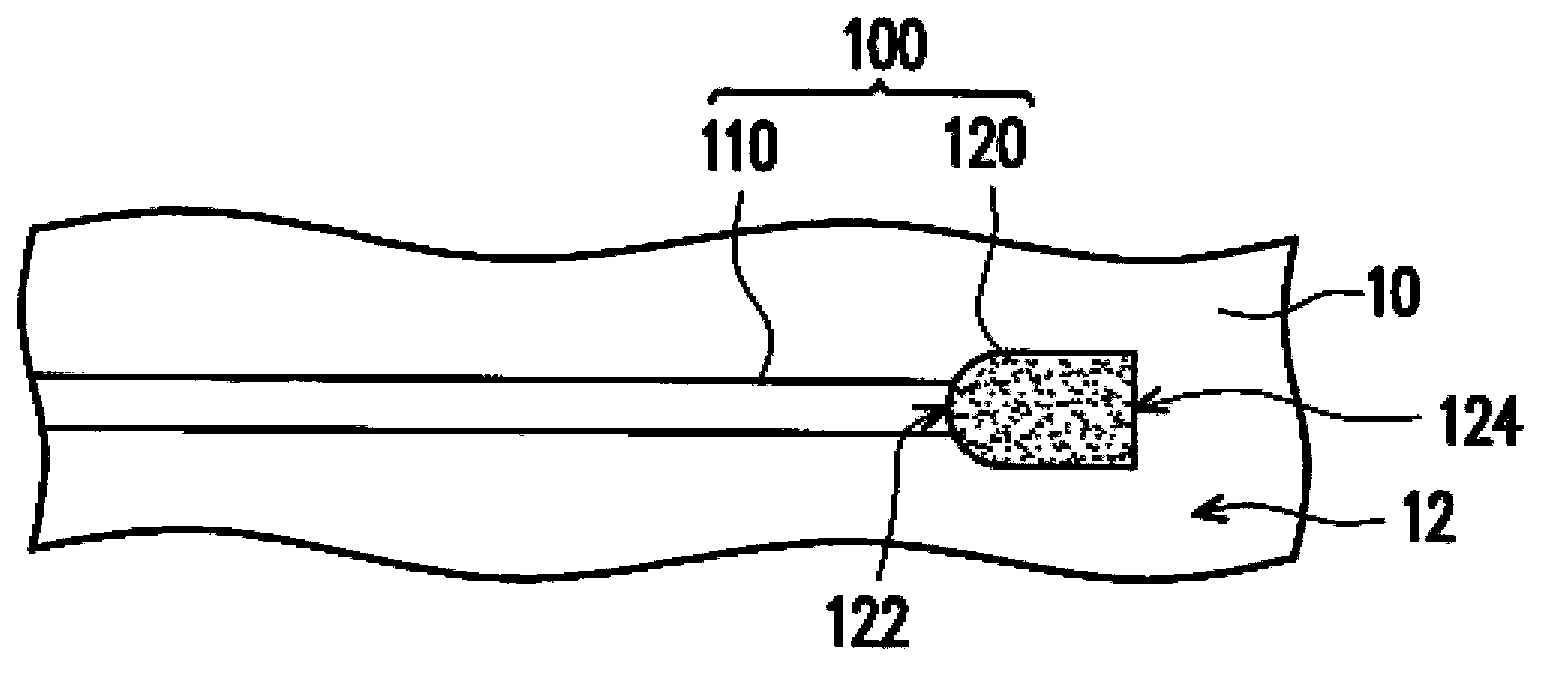
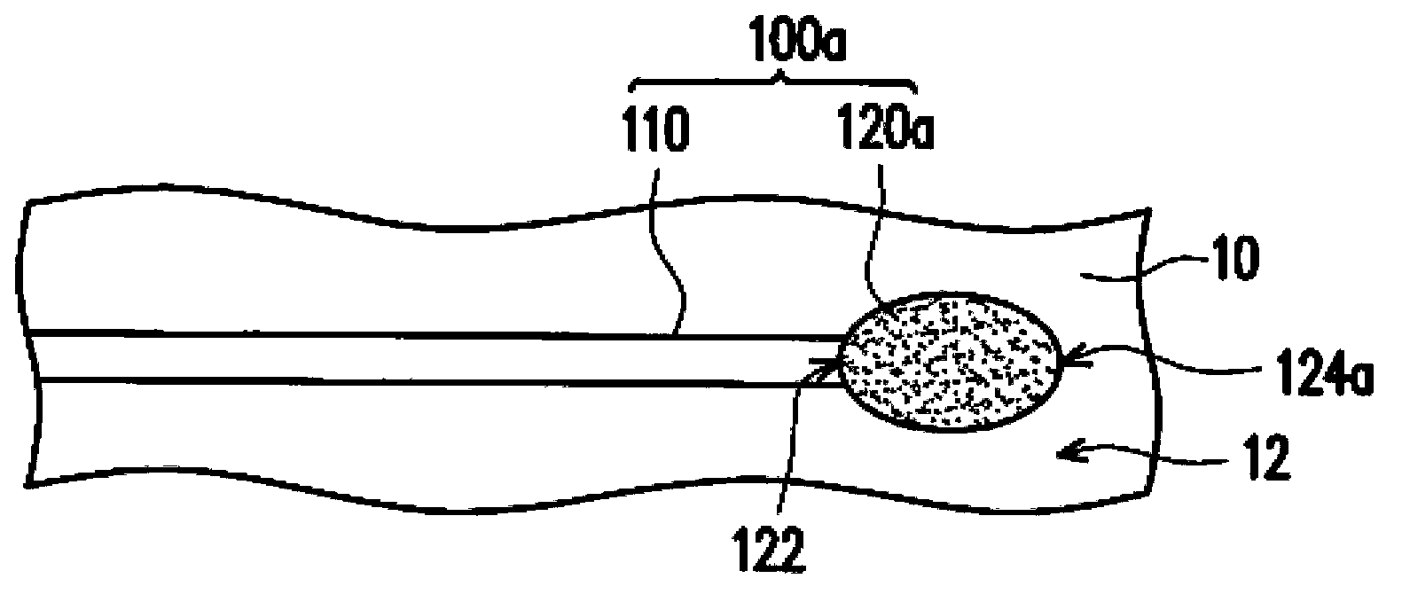
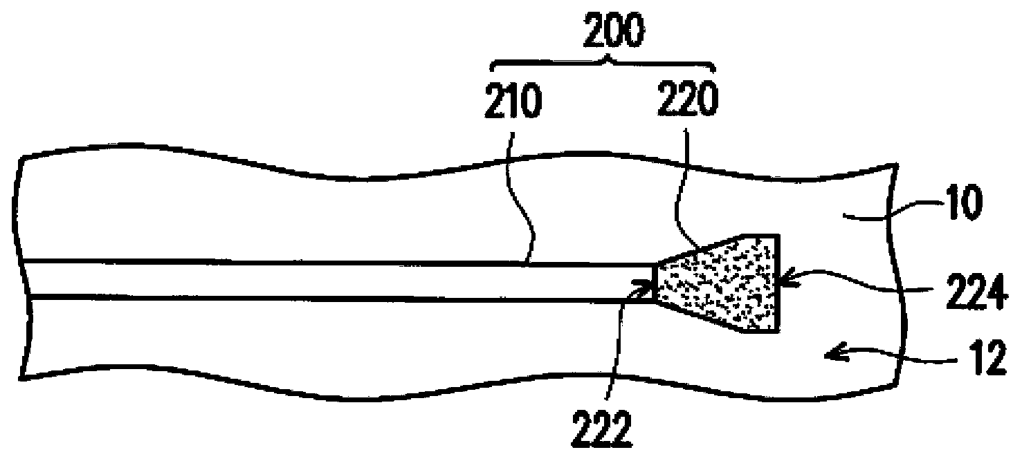
[0043] figure 1 It is a schematic partial top view of a connection structure of a circuit board according to an embodiment of the present invention. Please refer to figure 1 , in this embodiment, the connection structure 100 of the circuit board 10 includes at least one connection trace 110 (only one connection trace 110 is schematically shown here) and at least one connection pad 120 (only one connection trace 110 is schematically shown here) a connection pad 120). The connection traces 110 are disposed on a surface 12 of the circuit board 10 , and the connection pads 120 are also disposed on the surface 12 of the circuit board 10 . The connection pad 120 has a first end surface 122 and a second end surface 124 opposite to each other. The first end surface 122 is a convex curved surface and is connected to the connection trace 110 , while the second end surface 124 of the connection pad 120 in this embodiment is a plane. The cross-sectional area of ​​the connection pad 12...


PUM


Abstract

A connecting structure of a circuit board is provided. The connecting structure includes at least one connecting trace and at least one connecting pad. The connecting trace and the connecting pad are disposed on a surface, or inside of the circuit board. The connecting pad has a first end surface and a second end surface at two opposite end surfaces thereof. The first end surface is a convex curved surface and connected to the connecting trace, and a cross section area of the connecting pad is gradually increased from the first end surface.

Description

technical field [0001] The invention relates to a connection structure, in particular to a circuit board connection structure. Background technique [0002] The connection traces used to electrically connect the two terminals usually maintain the same cross-sectional area or similar cross-sectional areas on or within the printed circuit board and the package substrate, so the characteristic impedance of the connection traces can be kept the same. Especially in high-speed signal transmission and high-frequency signals, better impedance matching between the two terminals is necessary in circuit design, because the mismatched impedance between the two terminals will cause signal reflection and degradation Signal transmission quality. [0003] The prior art signal transmission structure at least includes a connection pad and a connection trace. The connection traces are connected to the connection pads, and the connection pads are suitable for connecting electrodes of the elec...

Claims


Application Information

Patent Timeline
Patent Type & Authority Applications(China)
IPC IPC(8): H05K1/11
CPCH05K1/025H05K1/111H05K2201/0939H05K2201/09727Y02P70/50
Inventor 黄信贸
Owner NAN YA TECH
Learn More