List mode dynamic image reconstruction

An image reconstruction and image technology, applied in the field of nuclear imaging and image motion compensation, can solve the problem of image noise and so on

Inactive Publication Date: 2014-01-22
KONINKLJIJKE PHILIPS NV
View PDF5 Cites 9 Cited by
  • Summary
  • Abstract
  • Description
  • Claims
  • Application Information

AI Technical Summary

Problems solved by technology

As a result, the "phase" image is sometimes noisy d

Method used


Image

  • List mode dynamic image reconstruction
  • List mode dynamic image reconstruction
  • List mode dynamic image reconstruction

Examples


Embodiment Construction

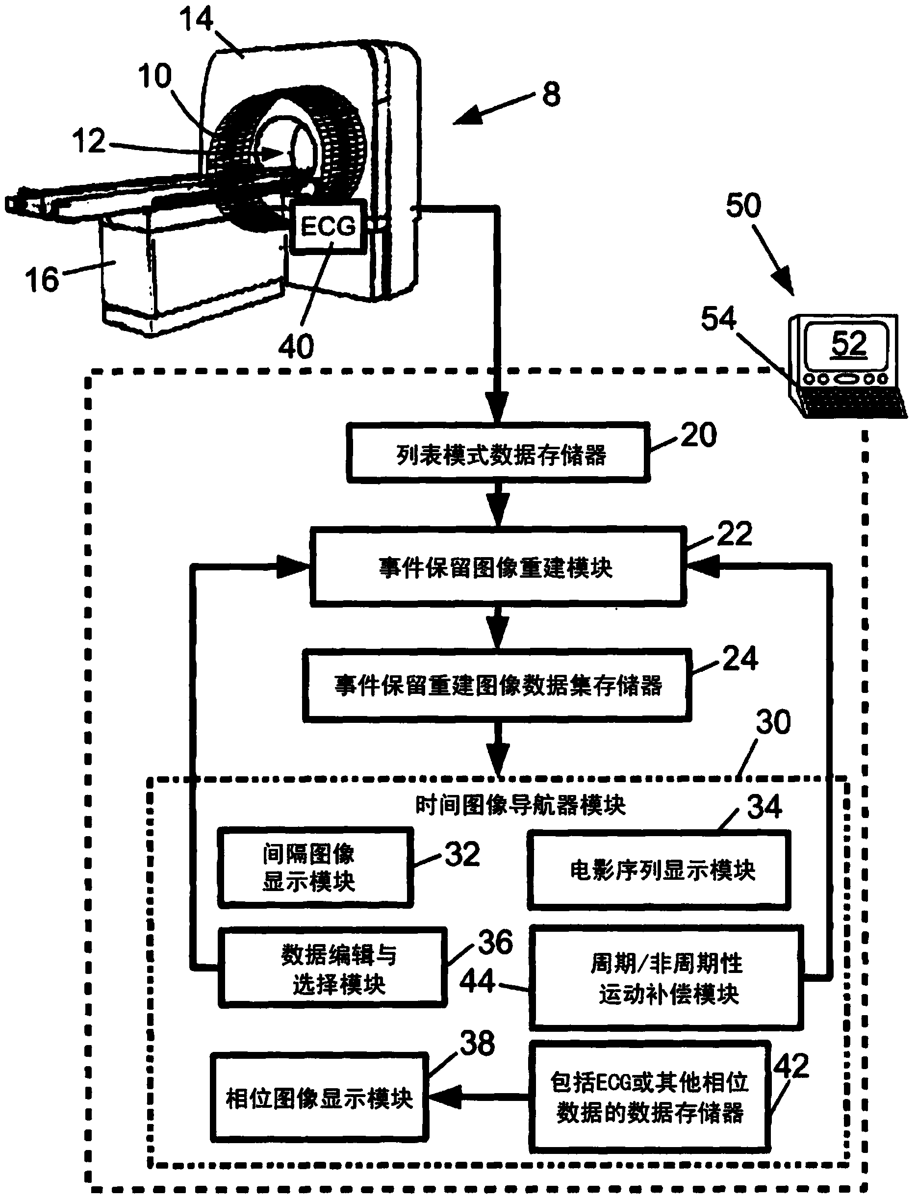
[0028] refer to figure 1 , a positron emission tomography (PET) scanner 8 comprising a plurality of radiation detectors 10 arranged to view an imaging region 12 . exist figure 1In , a plurality of radiation detectors 10 are arranged in several rings of detectors in the axial direction; however, other arrangements of radiation detectors may be used. Furthermore, it will be appreciated that a plurality of radiation detectors 10 are diagrammatically illustrated; typically the radiation detectors are housed within the housing 14 of the scanner 8 and are therefore not visible from the outside, and typically each ring of radiation detectors Consists of hundreds or thousands of radiation detectors. In some PET scanners only one ring of radiation detectors is provided, in others two, three, four, five or more rings of radiation detectors are provided. It will be appreciated that moveable SPECT or PET probes may be used at appropriate places within the exemplary detector circle to a...


PUM


Abstract

A nuclear imaging apparatus (8) acquires nuclear imaging data comprising events wherein each event records at least spatial localization information and a timestamp for a nuclear decay event. An event-preserving image reconstruction module (22) reconstructs the nuclear imaging data using an event-preserving reconstruction algorithm to generate an image represented as an event-preserving reconstructed image dataset (ID) comprising for each event the timestamp and at least one spatial voxel assignment. One or more structures are identified in the image and independent motion compensation is performed for each structure. In one approach, an events group is identified corresponding to the structure comprising events assigned to the structure by the event-preserving reconstructed image dataset; a time binning of the events of each events group is optimized based on a motion profile for the structure; time bin images are generated; and the structure is spatially registered in the time bin images.

Description

technical field [0001] The following relates to the field of nuclear imaging, the field of positron emission tomography (PET) imaging, the field of single photon emission computed tomography (SPECT) imaging, the field of image motion compensation, and related fields. Background technique [0002] In nuclear imaging, radiation detectors are placed around the subject to detect nuclear decay events. Each event is localized to a line of response (LOR) in the case of positron emission tomography (PET), or to a projected line or small-angle cone ( are generally referred to herein as "projections"). In the case of PET imaging with time-of-flight (TOF) capability, the small time difference between the detection of two oppositely directed 511 keV gamma rays is used to localize electron-positron annihilation events further along the LOR. Typically, this location is represented by a Gaussian or other statistical distribution "along" the LOR, with a Gaussian peak at the most likely lo...

Claims


Application Information

Patent Timeline
IPC IPC(8): G06T11/00
CPCG06T11/006G06T2211/412G06T7/20G06T11/005
Inventor S·普雷弗尔哈尔J·布雷多诺A·珀金斯P·奥利维尔
Owner KONINKLJIJKE PHILIPS NV
Why Eureka
Try Eureka