


Quick Research
Generate reliable direction feasibility study reports for your R&D in just a few steps.

Technical Q&A
Discover and master advanced knowledge NOW. Basics, ideas, possibilities, all at once.

Find Solutions
As an expert in R&D theories, this can generate solutions to your technical problems instantly.

Evaluate Feasibility
Analyze your overall solution with one click, know your potential R&D risks in advance.

Monitor Landscape
Get weekly tech updates, stay abreast of the latest tech innovations and key insights.
Power supply with tickle pulse injection
A technology of pulse and power supply, applied in amplifiers with semiconductor devices/discharge tubes, electrical components, and adjusting electrical variables, etc., can solve problems such as poor control
- Summary
- Abstract
- Description
- Claims
- Application Information
AI Technical Summary
Problems solved by technology
Method used
Image

Examples
Embodiment Construction
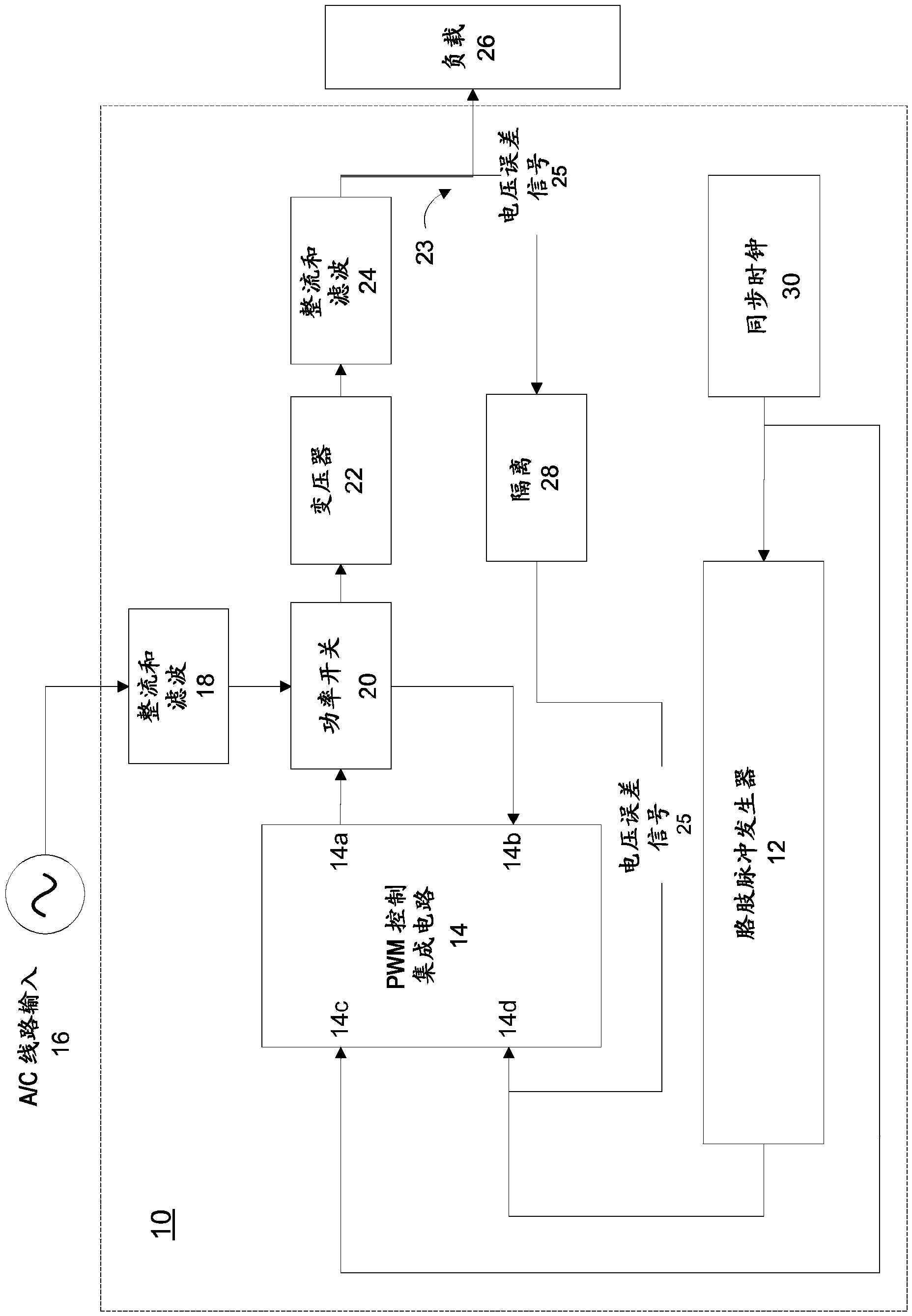
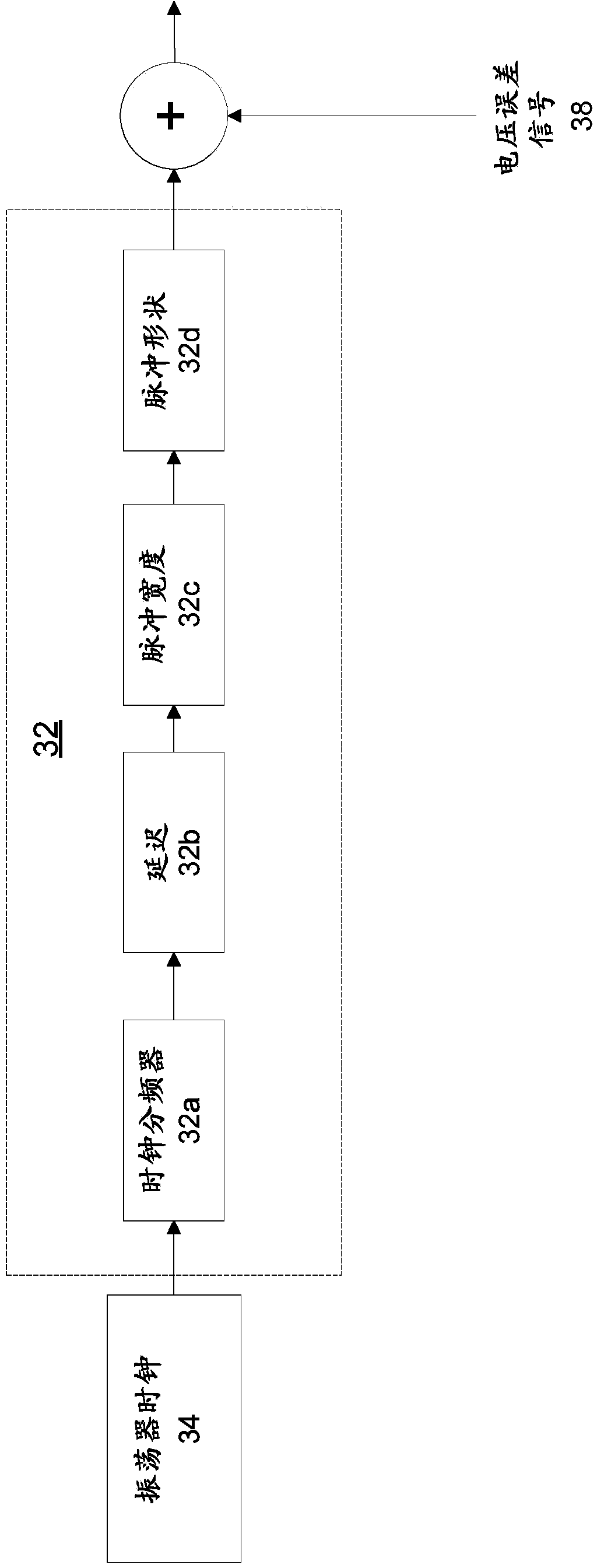
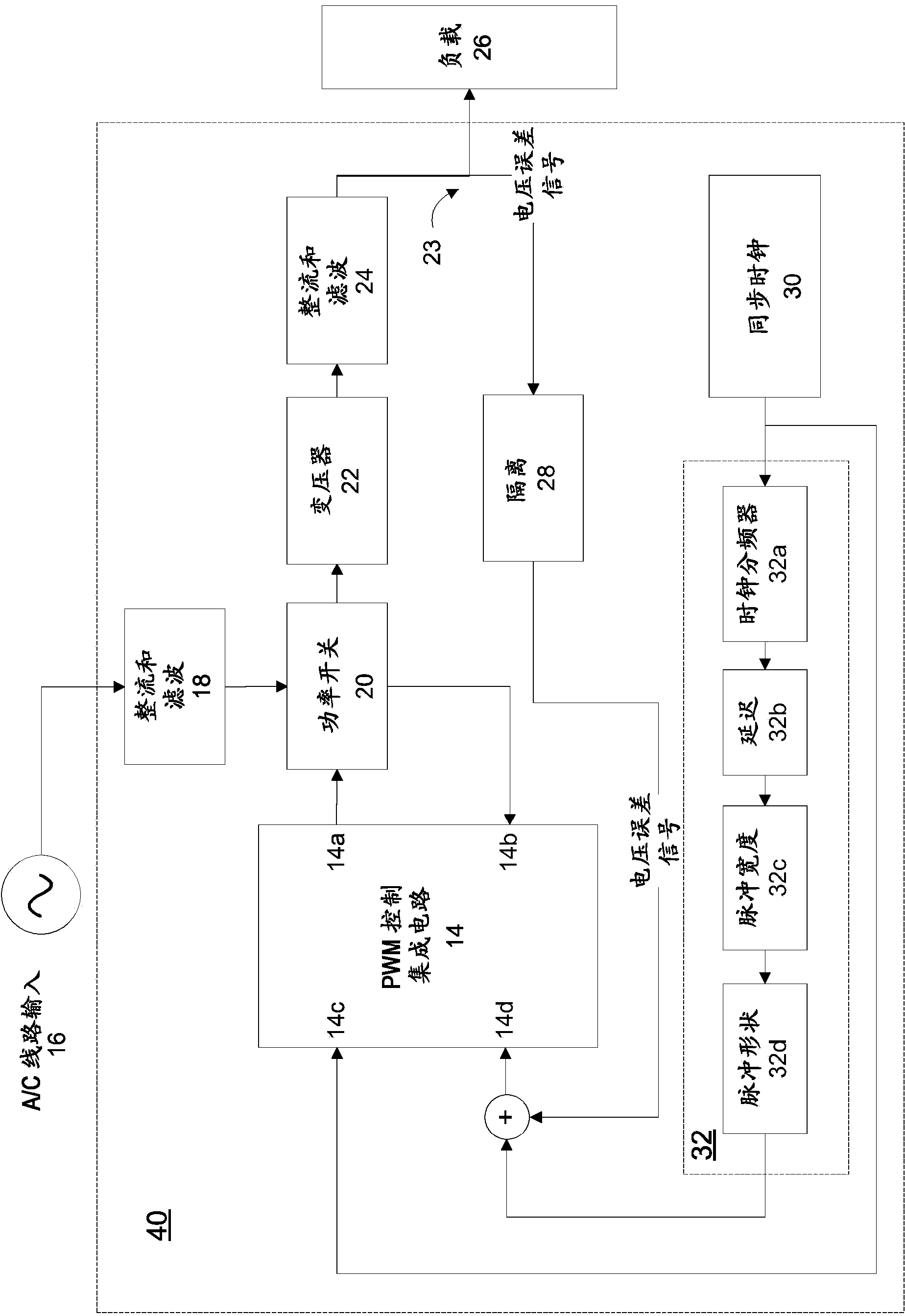
[0017] Such as figure 1 As shown in , the power supply 10 includes a tickle pulse generator 12 that periodically injects a "ticker" signal into a pulse width modulator (PWM) controller 14 to provide a pulse width modulator (PWM) controller 14 when the power supply 10 is lightly loaded (e.g. , the load draws 10% or less of the full power capacity of the power supply) to trigger a switching event. The PWM controller 14 includes four terminals: (i) PWM output terminal 14a, (ii) current sense input terminal 14b, (iii) clock input terminal 14c, and (iv) current command input terminal 14d.
[0018] The power supply 10 also includes an alternating current (A / C) line input 16 that is fed through a rectification and filtering stage 18 and delivered to a power switch 20 . The output of the power switch 20 is passed to a transformer 22 and finally to another rectification and filtering stage 24 where it is passed to an output node 23 . The output node 23 is connected to a variable load...
PUM
 Abstract
Description
Claims
Application Information
 - R&D Engineer
- R&D Manager
- IP Professional
- Industry Leading Data Capabilities
- Powerful AI technology
- Patent DNA Extraction
Browse by: Latest US Patents, China's latest patents, Technical Efficacy Thesaurus, Application Domain, Technology Topic, Popular Technical Reports.
© 2024 PatSnap. All rights reserved.Legal|Privacy policy|Modern Slavery Act Transparency Statement|Sitemap|About US| Contact US: help@patsnap.com