Hydraulic excavator energy-conservation control system

An energy-saving control system, hydraulic excavator technology, applied in the direction of earth mover/shovel, construction, etc., can solve the problems that affect the reliability of the system equipment, the working life of the hydraulic components, the rise of the system temperature, and the high production cost, so as to improve the energy consumption. Utilization rate, fuel consumption reduction, space saving effect

Active Publication Date: 2014-01-29
XCMG EXCAVATOR MACHINERY
View PDF6 Cites 8 Cited by
  • Summary
  • Abstract
  • Description
  • Claims
  • Application Information

AI Technical Summary

Problems solved by technology

[0002] With the development of industrial technology around the world, as an efficient earthwork construction machine, the role of hydraulic excavators in engineering construction is becoming more and more obvious; the working devices of hydraulic excavators have large mass and large inertia. Generally, a throttle valve is installed in the oil return direction of the rodless cavity of the boom cylinder to limit the lowering speed of the boom. However, with this structure, most of the gravitational potential energy of the working device will It will be converted into heat energy at the throttle port, resulting in waste of energy and rise in system temperature, thereby affecting the reli

Method used


Image

  • Hydraulic excavator energy-conservation control system

Examples


Example Embodiment

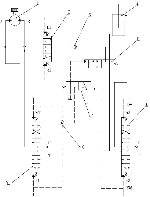
[0012] The present invention will be further described below in conjunction with the drawings.

[0013] Such as figure 1 Shown: The present invention includes a swing motor 1, a boom cylinder 4, a boom main control valve 6 and a swing motor main control valve 9, and also includes a three-position four-way hydraulic control reversing valve 2, a one-way valve 3, and a three-position three-way valve. The main hydraulic control valve 5, the two-position three-way hydraulic pilot pilot valve 7 and the shuttle valve 8; the three-position four-way hydraulic control valve 2 is connected to the working oil circuit of the rotary motor 1, and the three-position four-way hydraulic The pilot oil circuit of the directional control valve 2 is connected to the pilot oil circuit of the main control valve 9 of the swing motor, and the two-position three-way hydraulic control main directional valve 5 is connected to the rodless cavity of the boom cylinder 4 and the boom main control valve 6 The on...


PUM


Abstract

The invention discloses a hydraulic excavator energy-conservation control system. A three-position four-way hydraulic control reversing valve is connected to a working oil path of a rotary motor, wherein a pilot-operated oil path of the three-position four-way hydraulic control reversing valve is connected with a pilot-operated oil path of a rotary motor main control valve; a two-position three-way hydraulic control main reversing valve is connected to a working oil path of a boom cylinder rodless cavity, wherein a one-way valve is connected between the two-position three-way hydraulic control main reversing valve and the three-position four-way hydraulic control reversing valve, a two-position three-way hydraulic control pilot-operated reversing valve is connected between an oil outlet of a shuttle valve and the two-position three-way hydraulic control main reversing valve and connected with a boom main control valve which is used for controlling a boom to drop the pilot-operated oil paths, and the shuttle valve is connected to the pilot-operated oil paths at the two ends of the rotary motor main control valve. According to the hydraulic excavator energy-conservation control system, when a hydraulic excavator carries out composite operation of boom descending and rotation, the gravitational potential energy produced in the boom descending process can be transferred and supplied to the rotary motor in the form of hydraulic energy which can be used as an auxiliary power source of the rotary motor, so that space is saved, and cost is reduced.

Description

technical field [0001] The invention relates to an energy-saving control system for a hydraulic excavator, which belongs to the technical field of energy-saving control for hydraulic excavators. Background technique [0002] With the development of industrial technology around the world, as an efficient earthwork construction machine, the role of hydraulic excavators in engineering construction is becoming more and more obvious; the working devices of hydraulic excavators have large mass and large inertia. Generally, a throttle valve is installed in the oil return direction of the rodless cavity of the boom cylinder to limit the lowering speed of the boom. However, with this structure, most of the gravitational potential energy of the working device will It will be converted into heat energy at the throttle port, resulting in waste of energy and rise in system temperature, which in turn affects the reliability of system equipment and the working life of hydraulic components....

Claims


Application Information

Patent Timeline
IPC IPC(8): E02F9/20
Inventor 刘合涛韩立志费树辉张飞高春生岳苏华
Owner XCMG EXCAVATOR MACHINERY
Why Eureka
Try Eureka