
A method of manufacturing a semiconductor device using a dummy gate

A dummy gate, semiconductor technology, used in semiconductor devices, semiconductor/solid-state device manufacturing, electrical components, etc., can solve problems such as device performance impact and device damage, and achieve the effects of eliminating dents, improving process processes, and widening operating range.

Active Publication Date: 2017-06-16
SEMICON MFG INT (SHANGHAI) CORP
View PDF5 Cites 0 Cited by
  • Summary
  • Abstract
  • Description
  • Claims
  • Application Information

AI Technical Summary

Problems solved by technology

Usually, dry etching is used to remove the gate electrode layer on the dummy gate, but the dry etching in this step will often cause unnecessary damage to the device, especially the surface of the interlayer dielectric layer will be recessed, thereby affecting the performance of the fabricated device
[0003] However, there is currently no way to overcome the above problems in the process of manufacturing semiconductor devices using dummy gates.

Method used


Image

  • A method of manufacturing a semiconductor device using a dummy gate
  • A method of manufacturing a semiconductor device using a dummy gate
  • A method of manufacturing a semiconductor device using a dummy gate

Examples


Embodiment Construction

[0023] In the following description, numerous specific details are given in order to provide a more thorough understanding of the present invention. It will be apparent, however, to one skilled in the art that the present invention may be practiced without one or more of these details. In other examples, some technical features known in the art are not described in order to avoid confusion with the present invention.

[0024] In order to thoroughly understand the present invention, detailed steps will be presented in the following description to illustrate the method of manufacturing semiconductor devices using dummy gates proposed by the present invention. Obviously, the practice of the invention is not limited to specific details familiar to those skilled in the semiconductor arts. Preferred embodiments of the present invention are described in detail below, however, the present invention may have other embodiments besides these detailed descriptions.

[0025] It should be...


PUM


Abstract

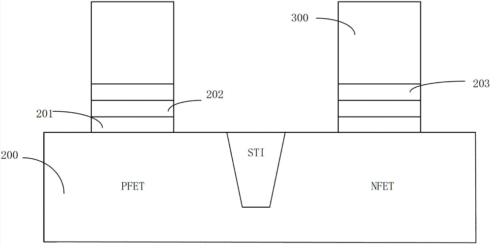
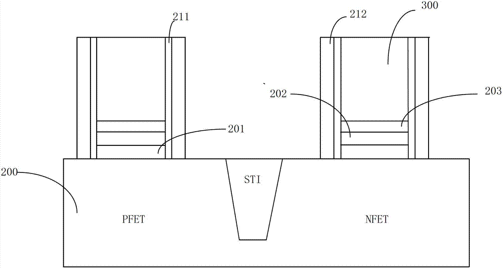
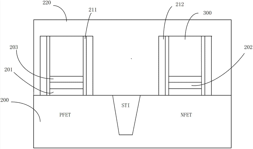
The invention provides a method for using dummy grids to manufacture a semiconductor device. The method includes: providing a semiconductor substrate containing a first area and a second area; forming the first dummy grid on the first area of the substrate, and forming the second dummy grid on the second area of the substrate, wherein each of the first dummy grid and the second dummy grid comprises a grid dielectric layer, a covering layer, a grid barrier layer and a grid electrode layer which are sequentially stacked; forming a source drain in the substrate; using wet etching to remove the grid electrode layer of the first dummy grid to form a channel; filling the channel to form a metal grid. By the method, recess, caused by steps such as etching during the dummy grid replacement process, of the surface of the inter layer dielectric (ILD) layer can be eliminated, wider operation range can be achieved, and accordingly device performance and the semiconductor device process are improved.

Description

technical field [0001] The present invention relates to the technical field of semiconductor manufacturing, more precisely, the present invention relates to a method for manufacturing semiconductor devices using dummy gates. Background technique [0002] In the process of manufacturing a semiconductor device using a dummy gate, it usually includes forming a dummy gate, source and drain on the substrate, and then removing the corresponding part on the dummy gate and filling the gap generated by removing this part of the dummy gate. Trench to form a series of steps such as gate. In this series of steps, the removal of the corresponding part of the dummy gate is an extremely critical step. Usually, dry etching is used to remove the gate electrode layer on the dummy gate, but the dry etching in this step will often cause unnecessary damage to the device, especially the surface of the interlayer dielectric layer will be recessed, This affects the performance of the fabricated d...

Claims


Application Information

Patent Timeline
Patent Type & Authority Patents(China)
IPC IPC(8): H01L21/28H01L21/8238
CPCH01L21/28008H01L21/823437
Inventor 张海洋孟晓莹
Owner SEMICON MFG INT (SHANGHAI) CORP
Learn More