Equipment cabinet and communication equipment

A technology for cabinets and cabinets, which is applied in the direction of cooling/ventilation/heating transformation, etc. It can solve the problems of poor product reliability, poor safety and reliability, and personal injury cabinets, so as to save costs and use costs, improve the overall stress situation, improve The effect of the duct structure

Inactive Publication Date: 2014-01-29
HUAWEI TECH CO LTD
View PDF4 Cites 7 Cited by
  • Summary
  • Abstract
  • Description
  • Claims
  • Application Information

AI Technical Summary

Problems solved by technology

[0007] Since the air conditioner itself contains components such as compressors, condensers, and evaporators, the air conditioner itself is relatively heavy, and the installation on the cabinet door 12' will increase the load bearing of the cabinet hinges, causing the cabinet door to appear "hanging foot phenomenon", resulting in the cabinet door 12' 'The opening and closing of the door is not smooth, and in serious cases, there will be problems such as water leakage and the failure to open and close the cabinet door 12'; during the production process, when the cabinet is in the open state, due to the heavy weight of the air conditioner, the cabinet is easy to tip over, causing personal injury or cabinet damage, and poor safety and reliability
[0008] Moreover, the distribution of the air outlet 101' and the return air outlet 102' of the internal circulation are all located on the cabinet door 12'. At the four corners of the cabinet, the cold air reaches less and the temperature is higher, forming a "hot zone" (so-called hot zone, referring to The area where the air duct inside the cabinet does not pass, the cold air cannot reach, and the temperature in this area is significantly higher than other areas inside the cabinet), the temperature in the cabinet is uneven, and the performance and life of the energy storage equipment and other components in the "hot area" are affected. poor reliability

Method used


Image

  • Equipment cabinet and communication equipment
  • Equipment cabinet and communication equipment
  • Equipment cabinet and communication equipment

Examples


Embodiment 1

[0035] A cabinet provided by an embodiment of the present invention may be an energy storage cabinet or other cabinets that have higher requirements on temperature regulation. The cabinets can be used as power storage cabinets, outdoor power supply equipment cabinets, and outdoor air-conditioning cabinets in any other field. In this embodiment, an energy storage cabinet is taken as an example to illustrate the beneficial effects of the present invention.

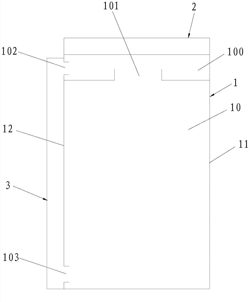
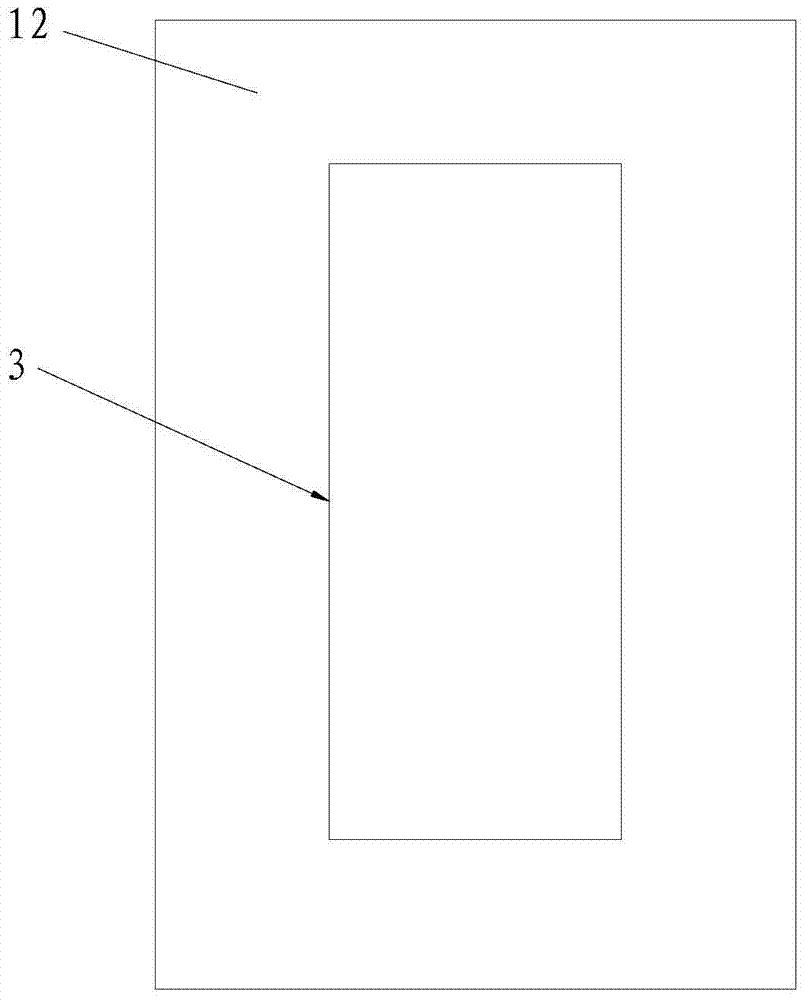
[0036] Such as figure 2 with image 3As shown, the above-mentioned cabinet includes a cabinet body 1 with an inner cavity 10 and an air conditioner 2 for generating cooling airflow. The inner cavity 10 may be provided with energy storage devices and other components, and the energy storage devices may be batteries. The air conditioner 2 is arranged on the upper or lower end of the cabinet body 1, so that the heavy air conditioner 2 can completely act on the cabinet body 1, and the air conditioner 2 does not need to be arr...

Embodiment 2

[0050] It is different from the position and air duct components of the internal circulation air outlet, the internal circulation middle air outlet, and the internal circulation return air outlet in Embodiment 1, such as Image 6 with Figure 7 As shown, in this embodiment, the air duct part 3a is used to guide the cooling airflow of the inner circulation air outlet 101a to the inner circulation intermediate air outlet 103a, and the inner circulation air outlet 101a is arranged on the upper part of the cabinet door 12a or the upper part of the side of the cabinet body 1a, The inner circulation middle tuyere 103a is arranged on the lower part of the cabinet door 12a or the lower part of the side of the cabinet body 1a, and the inner circulation air outlet 101a and the inner circulation middle tuyere 103a can be set on the same side of the cabinet body 1a. One end of the air duct part 3a communicates with the inner circulation air outlet 101a, and the other end of the air duct p...

Embodiment 3

[0052] Different from the positions and air duct components of the internal circulation air outlet, the internal circulation middle air outlet, and the internal circulation return air outlet in Embodiment 1, in this embodiment, such as Figure 9As shown, the inner circulation air outlet 101b is arranged on the upper part of the cabinet door 12b or the upper part of the side of the cabinet body 1b, the inner circulation middle air outlet 103b is arranged on the lower part of the cabinet door 12b or the lower part of the side of the cabinet body 1b, and the inner circulation air outlet 101b is connected to the inner The circulating intermediate air outlet 103b can be arranged on the same side of the cabinet body 1b. The inner circulation air return port 102b is set at the lower end of the air conditioner heat exchange cavity 100b and communicates with the upper end of the inner cavity 10b. One end of the air duct part 3b communicates with the inner circulation air outlet 101b, an...


PUM


Abstract

The invention belongs to the technical field of equipment cabinets and discloses an equipment cabinet and communication equipment. The equipment cabinet comprises a cabinet body and an air conditioner which is arranged at the upper end or the lower end of the cabinet body. An air conditioner heat exchanging cavity is arranged at one end, close to the air conditioner, of the equipment cabinet. An inner circulation air outlet and an inner circulation air returning opening which are communicated with the air conditioner heat exchanging cavity are formed in the cavity body. The cavity body is further provided with an inner circular middle air opening. An air channel part which is used for guiding air flow at the inner circulation middle air opening to the inner circulation air returning opening or for guiding cooling air flow to the inner circulation middle air opening is arranged on the side face of the cabinet body. The communication equipment comprises the equipment cabinet. According to the equipment cabinet and the communication equipment, even temperature in the equipment cabinet can be guaranteed, and safety and reliability are high.

Description

technical field [0001] The invention belongs to the technical field of cabinets, in particular to a cabinet and communication equipment. Background technique [0002] In the field of communication base stations, cabinets are widely used, such as energy storage cabinets. In order to reduce fuel consumption and save costs, hybrid power supply has become the main form of power supply. The energy storage cabinet with the battery inside is an essential and extremely important part of the hybrid power supply. The performance of the energy storage cabinet directly affects the charging and discharging performance and life of the battery. [0003] Energy storage cabinets mostly use air conditioners to adjust the internal temperature of the cabinet to adapt to different climates and environments, so that the battery can always work at the optimal temperature. In this case, the air outlet and return air outlet of the internal circulation of the air conditioner and the air duct inside...

Claims


Application Information

Patent Timeline
IPC IPC(8): H05K7/20
Inventor 苏京卫赵晓军赵喜勤
Owner HUAWEI TECH CO LTD
Why Eureka
Try Eureka