Battery pack with air duct structure and air cooling method

A technology for battery packs and air ducts, applied to secondary batteries, circuits, electrical components, etc., which can solve problems such as high manufacturing costs, complex liquid cooling system structures, and large local temperature differences, and achieve low cost and optimized air ducts Effect of structure, temperature balance

Pending Publication Date: 2022-04-01
SHANGHAI RUIPU ENERGY CO LTD
View PDF9 Cites 0 Cited by
  • Summary
  • Abstract
  • Description
  • Claims
  • Application Information

AI Technical Summary

Problems solved by technology

The traditional liquid cooling heat dissipation method uses a liquid cooling plate at the bottom of the battery module, and the cooling liquid is passed through the liquid cooling plate to cool the battery module. A thermally conductive silica gel with good thermal conductivity is pasted between the module and the liquid cooling plate. Although liquid cooling can complete the heat dissipation and cooling work of the battery pack, the structure of the liquid cooling system is complicated, and the manufacturing cost and use cost are high. More importantly, once the circulating cooling liquid in the battery box occurs Leakage and contact with live parts in the battery system will most likely cause serious safety accidents. At the same time, the liquid cooling plate is placed under the battery module, causing uneven heat dissipation, large local temperature differences, and poor heat dissipation

Method used


Image

  • Battery pack with air duct structure and air cooling method
  • Battery pack with air duct structure and air cooling method
  • Battery pack with air duct structure and air cooling method

Examples


Embodiment Construction

[0039] It should be understood that in the description of the present invention, the terms "center", "longitudinal", "transverse", "upper", "lower", "front", "rear", "left", "right", " The orientations or positional relationships indicated by "vertical", "horizontal", "top", "bottom", "inner" and "outer" are based on the orientations or positional relationships shown in the drawings, and are only for the convenience of describing the present invention and Simplified descriptions, rather than indicating or implying that the device or element referred to must have a particular orientation, be constructed and operate in a particular orientation, and thus should not be construed as limiting the invention. In addition, the terms "first", "second", etc. are used for descriptive purposes only, and should not be understood as indicating or implying relative importance or implicitly specifying the quantity of the indicated technical features. Thus, a feature defined as "first", "second...


PUM


Abstract

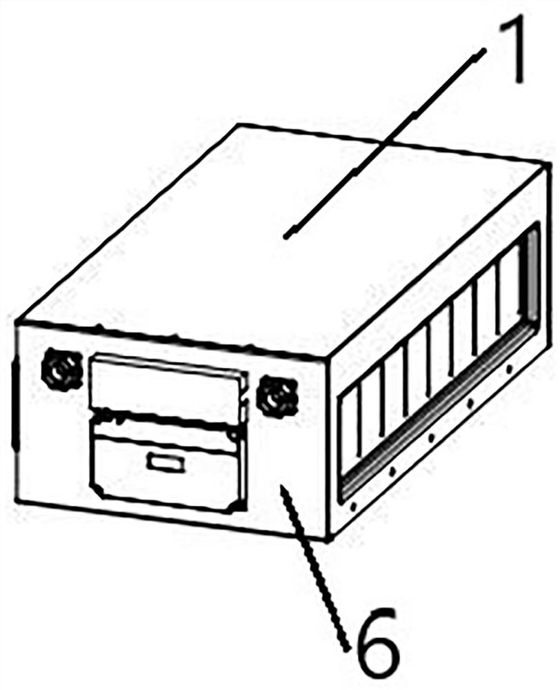
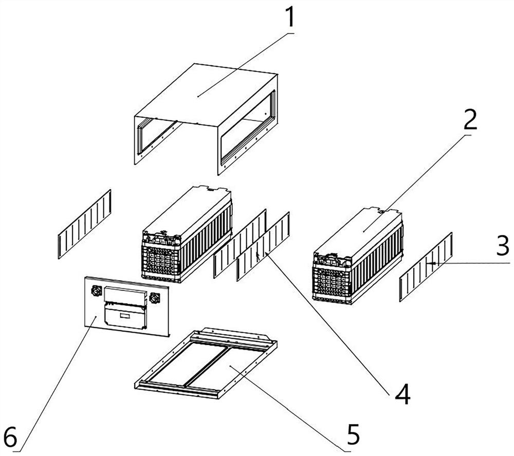
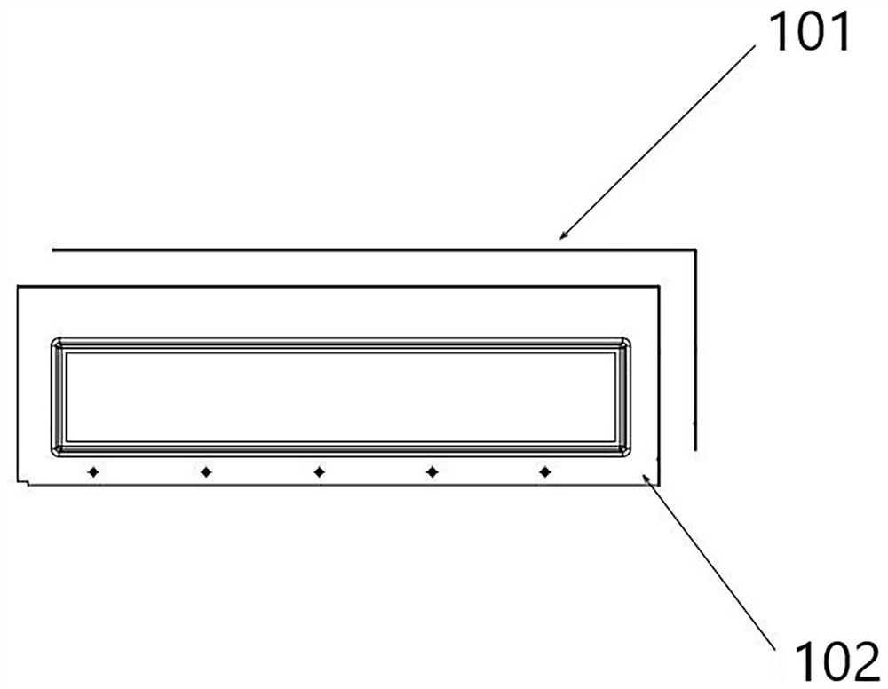
The invention provides a battery pack with an air duct structure and an air cooling method.The battery pack with the air duct structure comprises a box body and battery modules arranged in the box body, the opposite side walls of the box body are each provided with a first air control element, and at least one second air control element is arranged between every two adjacent battery modules; ventilation openings are formed in the first air control element and the second air control element; air enters the box body from the first air control element on one side, flows through the heat dissipation element and the second air control element and is discharged out of the box body from the first air control element on the other side. By arranging the first air control element, the heat dissipation element and the second air control element, the air ducts are optimized, a fan does not need to be installed on the battery pack, the multi-air-duct effect is achieved, and the multi-air-duct battery pack has the advantages of being simple in structure, fully utilizing space, being good in heat dissipation effect and the like.

Description

technical field [0001] The invention belongs to the technical field of batteries, and relates to a battery pack with an air channel structure and an air cooling method. Background technique [0002] At present, the field of new energy is gradually developing, and more container energy storage technologies are widely used in various fields. The market competition is more intense, containers with larger capacity, higher voltage, and higher current begin to appear, and battery packs are an indispensable part of them. The increase in current leads to greater heat generated by the battery pack during work. Traditional The natural heat dissipation method can no longer meet the requirements, thus introducing air cooling and liquid cooling. In traditional air cooling, each battery pack has a fan, blowing and sucking air on the front panel. The traditional liquid cooling heat dissipation method uses a liquid cooling plate at the bottom of the battery module, and the cooling liquid ...

Claims


Application Information

Patent Timeline
Patent Type & Authority Applications(China)
IPC IPC(8): H01M10/613H01M10/6563H01M10/6566H01M10/6555
CPCY02E60/10
Inventor 曹辉梁春欣王思远郁辰刘思侯敏
Owner SHANGHAI RUIPU ENERGY CO LTD
Why Eureka
Try Eureka