Shock absorbers for hydraulic systems

A hydraulic and pressure technology, applied in the direction of fluid pressure actuation system components, fluid pressure actuation devices, functional valve types, etc., can solve problems such as loss of shock absorbers

Active Publication Date: 2016-12-21
SCHAEFFLER TECH AG & CO KG
View PDF8 Cites 0 Cited by
  • Summary
  • Abstract
  • Description
  • Claims
  • Application Information

AI Technical Summary

Problems solved by technology

That is, the shock absorber loses its effect

Method used


Image

  • Shock absorbers for hydraulic systems
  • Shock absorbers for hydraulic systems
  • Shock absorbers for hydraulic systems

Examples


Embodiment Construction

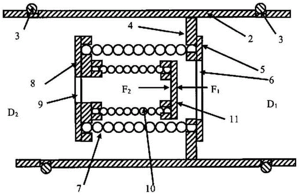
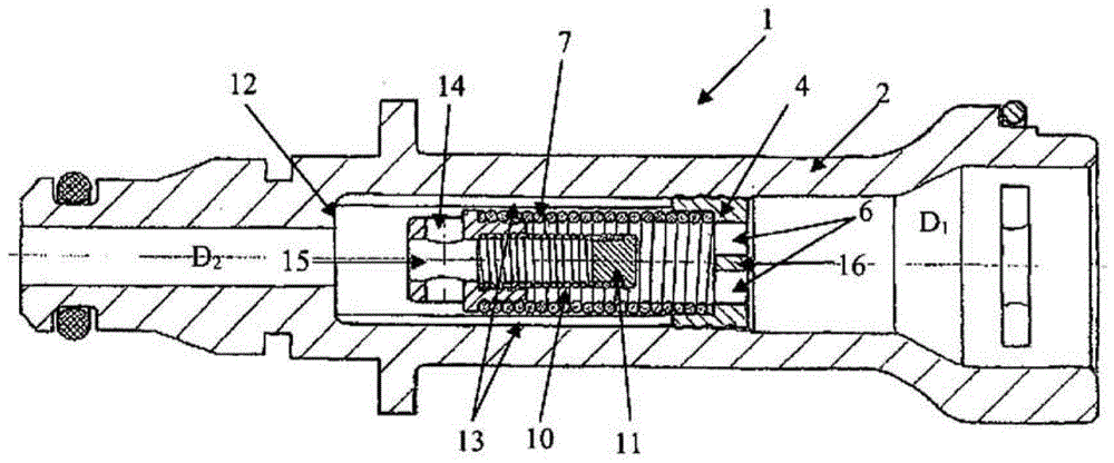
[0016] figure 1 A vibration absorber 1 according to the invention is shown which has a housing 2 which has on its outer circumference two grooves with sealing rings 3 arranged therein. which is figure 1 The embodiment in is suitable for insertion into a housing which is arranged in the flow path of the hydraulic section. For example the possibility arises that: will be based on figure 1 The shock absorber is inserted directly into the drive cylinder in order to thereby damp possible vibrations particularly effectively. Alternatively, it is of course also possible to configure the shock absorber according to the invention with its own housing and to be provided with corresponding connectors which are designed for connection to the pressure line of the hydraulic circuit and / or to the master cylinder or from the Cylinder connection.

[0017] Inside the housing 2 of the shock absorber 1 there is a partition 4 which has a partition opening 6 . Arranged in the partition opening...


PUM


Abstract

The invention relates to a device for damping pressure vibrations within a hydraulic system, wherein the hydraulic system comprises a master cylinder and a slave cylinder that are hydraulically interconnected by way of a pressure line through which a fluid flows, having a housing, which has an inlet opening, a flow path and an outlet opening for the hydraulic fluid, and wherein two 2 / 2-directional control valves are arranged parallel in the flow path in such a way that each conducting direction is directed oppositely to the other, wherein the 2 / 2-directional control valves are designed with helical springs, wherein the individual coils of the helical springs lie adjacent each other in the unstressed state and form a closed cylindrical barrel, and one of the two ends of the helical springs is tightly sealed.

Description

technical field [0001] The invention relates to a device for damping pressure oscillations within a hydraulic circuit. Background technique [0002] DE 101 06 958 shows a device for damping pressure oscillations that operates in the manner of a hose valve. However, hose valves require relatively much axial installation space. Furthermore, in order to seal the openings in the valve which are closed by means of the hose, a relatively high hose contact force is required on the inner or outer pipe, so that the necessary actuating forces of the hydraulic system increase relatively strongly and due to material and production fluctuate significantly due to tolerances in terms of Hose valves also have basic leaks that are difficult to overcome. [0003] Furthermore, the effectiveness of such devices for damping pressure oscillations is limited by their mode of action. If pressure oscillations occur at the valve during operation, briefly open the valve. The work necessary for th...

Claims


Application Information

Patent Timeline
Patent Type & Authority Patents(China)
IPC IPC(8): F15B21/00F16K15/14F16K17/196
CPCF15B13/027F15B21/008F16K15/145F16K17/196
Inventor L·伊艾兴P-Y·贝泰勒米R·韦尔特J·格拉本斯塔特尔
Owner SCHAEFFLER TECH AG & CO KG
Why Eureka
Try Eureka