Vision testing device using multigrid pattern

A visual inspection and lattice technology, which is applied in the direction of using optical devices, measuring devices, and optical testing for flaws/defects, can solve problems that easily lead to errors, cannot be distinguished, and inspections take a lot of time to achieve the effect of improving uniformity

Inactive Publication Date: 2014-01-29
MIRTEC
View PDF6 Cites 2 Cited by
  • Summary
  • Abstract
  • Description
  • Claims
  • Application Information

AI Technical Summary

Problems solved by technology

[0011] However, if figure 1 As shown, when an inspection object with a certain height is irradiated with light of grid stripes and then photographed from a plane angle, if the height of the inspection object is much higher than the interval of grid stripes, then it is impossible to distinguish Which of the grid stripes 1, 2, 3 irradiated on the upper part of the inspection object and the grid stripes 1-1, 2-1, 3-1 on the bottom is the same grid stripe at the beginning
[0012] Therefore, this factor is a factor that is likely to cause errors for the height inspection. In order to eliminate the above-mentioned error, it is necessary to perform a complicated calculation process during the height inspection, and at the same time, the inspection also takes a lot of time.

Method used


Image

  • Vision testing device using multigrid pattern
  • Vision testing device using multigrid pattern
  • Vision testing device using multigrid pattern

Examples


Embodiment Construction

[0038] Hereinafter, the configuration of the present invention will be described in detail with reference to the accompanying drawings.

[0039] Before the description, it needs to be explained that the terms used in this description and the claims are not limited to the meanings explained in the dictionary, and the inventor can properly define the concept of the terms in order to better explain his invention, so , the meanings or concepts of relevant terms shall be interpreted in accordance with the principle of conforming to the technical idea of ​​the present invention.

[0040] Therefore, the embodiments described in this specification and the structures shown in the drawings are only preferred embodiments of the present invention, and cannot fully reflect the technical idea of ​​the present invention. Therefore, various changes or modifications can be made to the present application.

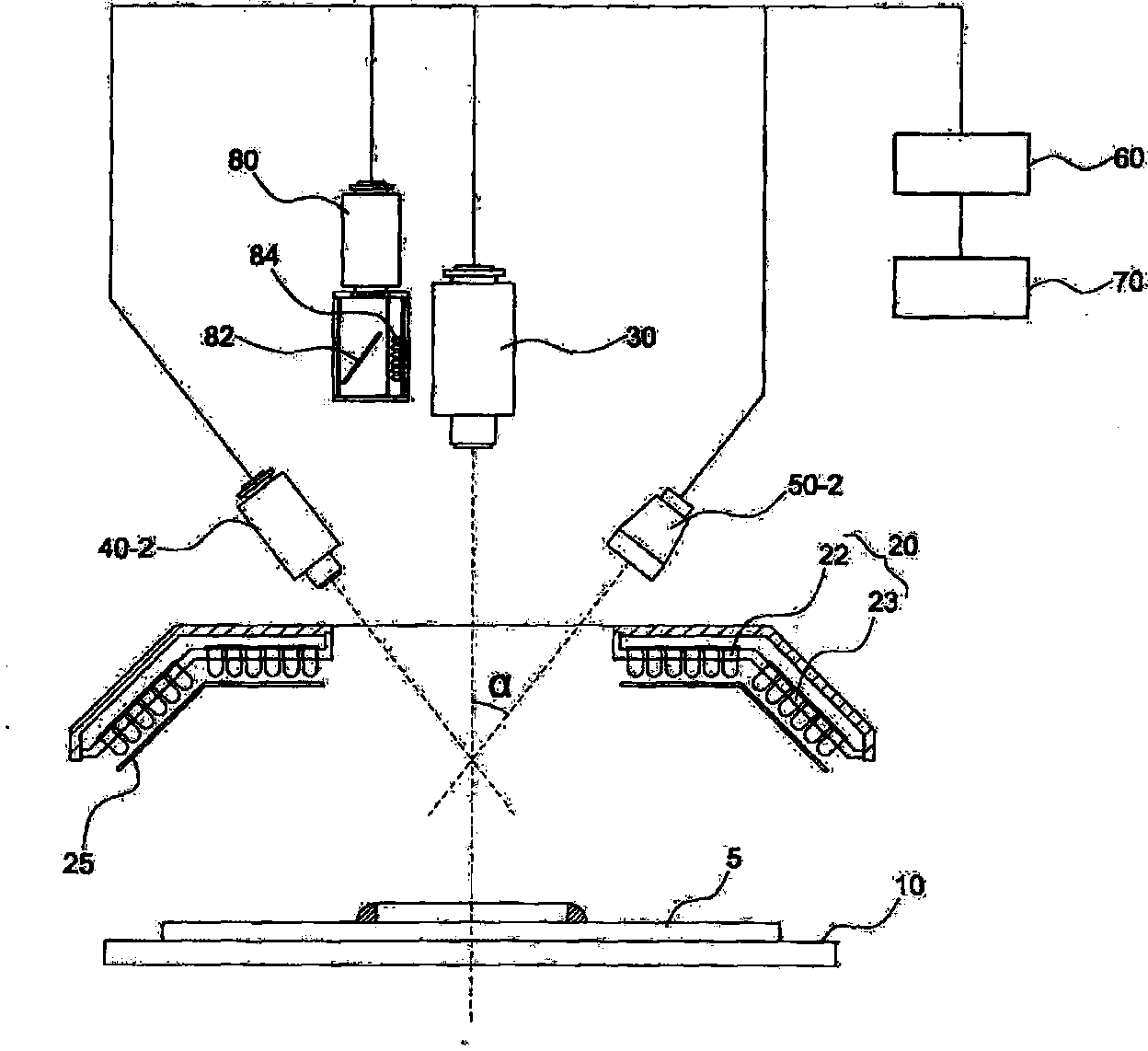
[0041] figure 2 is a schematic side view of a visual inspection device according to ...


PUM

PropertyMeasurementUnit
heightaaaaaaaaaa
heightaaaaaaaaaa

Abstract

The vision testing device of the present invention is a vision testing device for discriminating a satisfactory or a nonsatisfactory testing object by shooting a testing object assembled or mounted during the component assembly process, and comparing the image shot with a previously inputted target image, and comprises: a stage part for fixing or transferring the testing object to the testing location; a lighting part located on the upper portion of the stage part, for providing lighting to the testing object; a center camera part located in the center of the lighting part, for obtaining a 2-dimensional image of the testing object; a grid pattern irradiating part placed on the side section of the center camera part; a vision processing unit for reading the image shot at the center camera part and discriminating satisfactory or non-satisfactory testing objects; and a control unit for controlling the stage part, the grid pattern irradiating part, and the camera part, wherein the grid pattern irradiating part irradiates grid patterns each having periods of different intervals.

Description

technical field [0001] The present invention relates to a visual inspection device, in particular, to an object that can quickly and accurately measure the height of an inspection object by performing visual inspection using grid stripes with wider intervals and grid stripes with narrower intervals. Visual inspection device. Background technique [0002] In general, surface mount technology (SMT; Surface Mounting Technology) for assembling surface mount components such as printed circuit boards (PCBs) includes: technologies for miniaturization / integration of surface mount components (SMD; Surface Mounting Device) , The development of precision assembly equipment for the precise assembly of the above-mentioned surface mount components and the technology of using various assembly equipment. [0003] The surface mount production line consists of equipment such as surface mount machines and visual inspection devices. The surface mounter mentioned above is a device for mounting...

Claims


Application Information

Patent Timeline
Patent Type & Authority Applications(China)
IPC IPC(8): G01B11/25G01N21/88
CPCG01N21/95684G01B11/25G01B11/0608G01N2021/95638G01B11/2509G01B11/2513
Inventor 朴赞化吴尚珉金圣铉具滋明
Owner MIRTEC
Why Eureka
Try Eureka