
Measuring unit and gas analyzer

A technology of measurement unit and analysis device, which is applied to the construction details of measurement devices and gas analyzers, and analysis materials, etc., which can solve the problem of inability to obtain stable signals and measurement of light. internal issues

Inactive Publication Date: 2014-01-29
HORIBA LTD
View PDF5 Cites 11 Cited by
  • Summary
  • Abstract
  • Description
  • Claims
  • Application Information

AI Technical Summary

Problems solved by technology

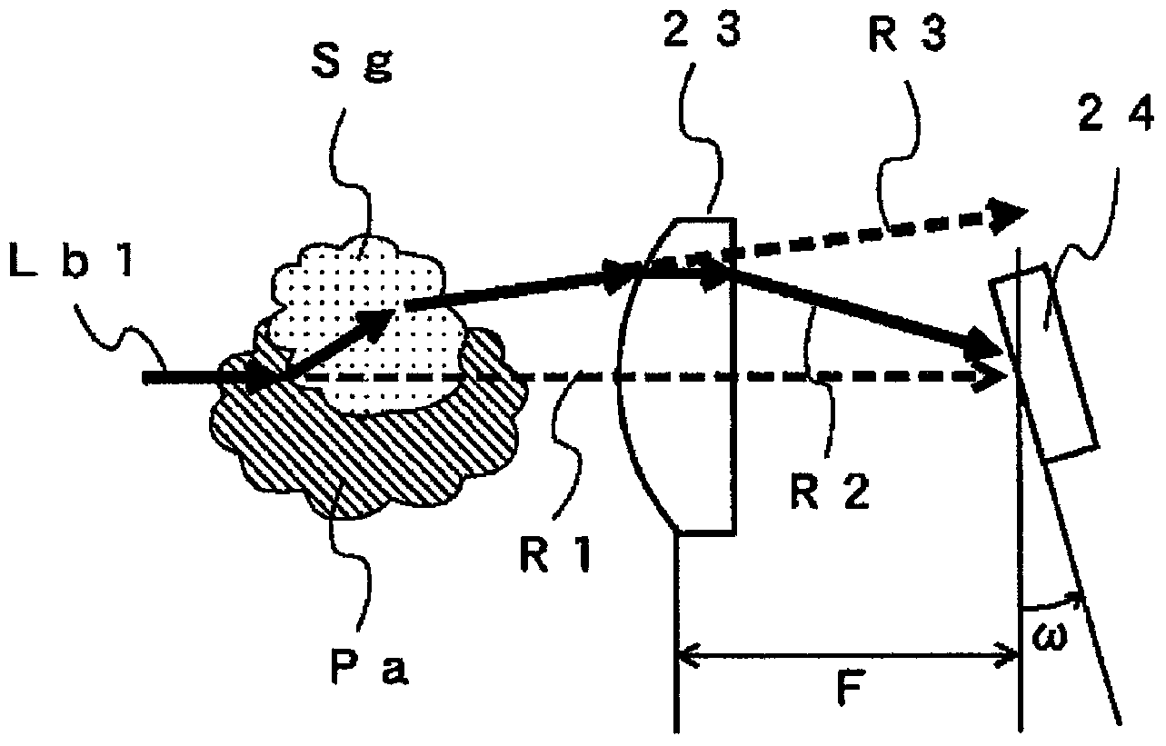
If the position of the irradiation point Lbp2 in such a light-receiving sensor moves, even if the light quantity of the measurement light Lb2 is fixed, for example, a stable signal cannot be obtained from the light-receiving sensor.
[0013] In addition, even if the same purge gas as the above-mentioned probe method is used in the gas analysis device of the open hole method, the measurement light may be refracted due to the thermal lens effect, and the irradiation point of the measurement light cannot be well placed on the light receiving sensor. In the receiving surface

Method used


Image

  • Measuring unit and gas analyzer
  • Measuring unit and gas analyzer
  • Measuring unit and gas analyzer

Examples


no. 1 Embodiment approach )

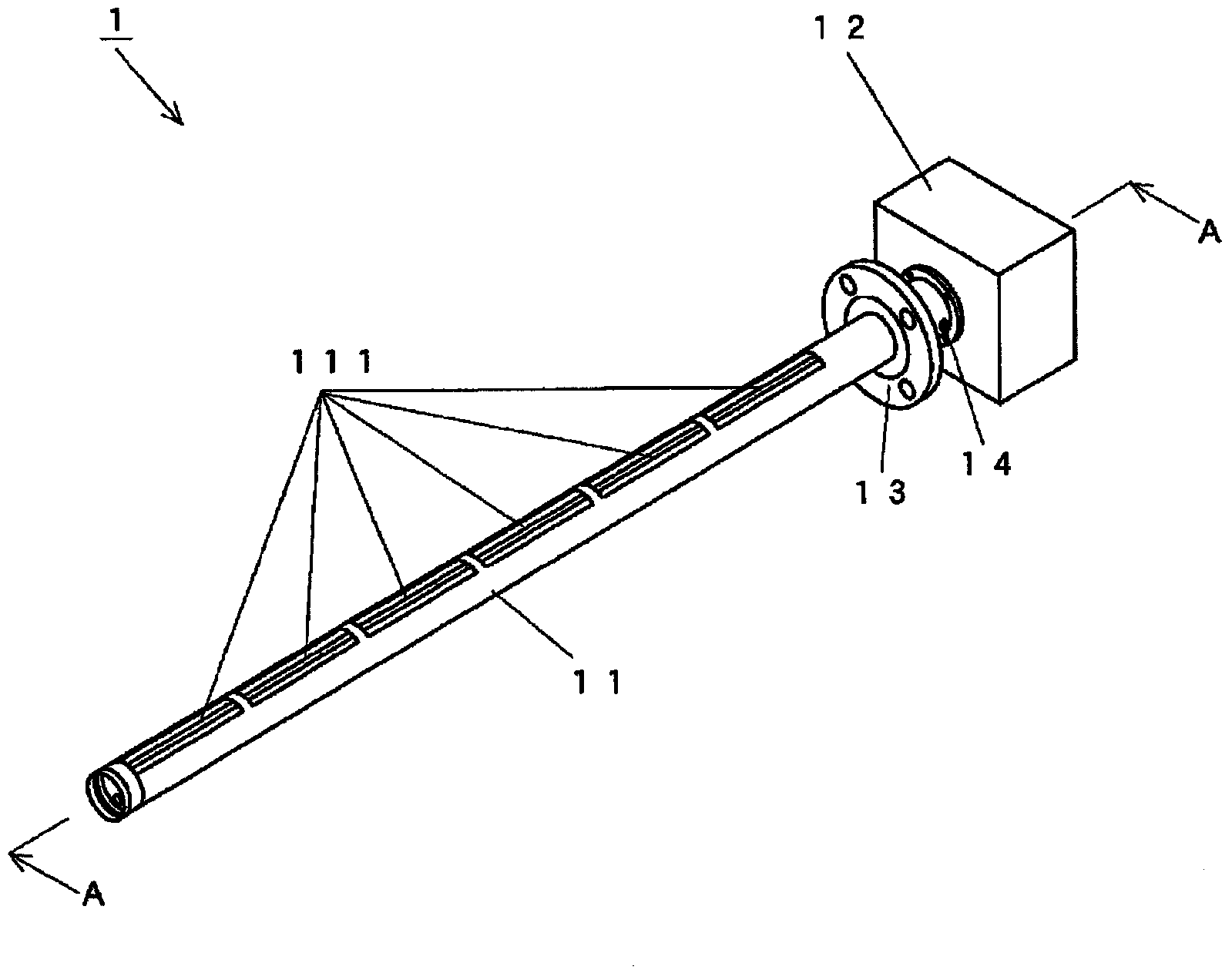
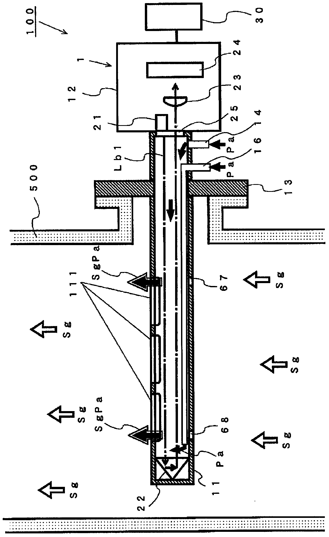
[0057] Next, the measurement unit 1 and the gas analysis device 100 using the measurement unit 1 will be described. The gas analysis device 100 is a so-called probe type gas analysis device, and the measurement unit 1 is a so-called probe unit. First, refer to figure 1 and figure 2 , the structure of the measurement unit 1 will be described. figure 1 It is an external configuration diagram of the measurement unit 1 of the first embodiment. also, figure 2 It is a sectional view showing the internal structure of the measurement unit 1 of the first embodiment. in addition, figure 2 is included figure 1 A diagram of the section A-A of the measuring cell 1 is shown. Such as figure 1 As shown, the measurement unit 1 includes a probe tube 11 , an optical unit 12 and a flange 13 .

[0058] The probe tube 11 is a cylindrical member, and is provided with an introduction hole 111 through which the sample gas Sg is introduced into the interior by diffusion. The material o...

no. 2 approach )

[0083] In the first embodiment described above, an example in which the present invention is applied to a probe-type measuring unit has been described, but the present invention may also be applied to an aperture-type measuring unit. Next, the measurement unit 2 of the second embodiment and the gas analysis device 200 using the measurement unit 2 will be described. In addition, the same reference numerals are assigned to the same structures as those of the above-mentioned first embodiment, and detailed description thereof will be omitted.

[0084] Figure 8 It is a sectional view showing the internal structure of the measurement unit 2 of the second embodiment. Such as Figure 8 As shown, the measuring unit 2 is composed of an oscillator unit 32 and a detector unit 33 formed as a single body. The oscillator unit 32 is installed on one side of the chimney 500 through which the sample gas Sg flows, and the detector unit 33 is installed on the other side of the chimney 500 so ...


PUM


Abstract

A measuring unit (1), which is used in an analyzer for analyzing the concentrations of predetermined components in a sample gas, is provided with: an irradiation part (21) that irradiates measuring light inside the sample gas; a light-receiving part (24) that receives the measuring light on a light-receiving surface; a purge air inlet (14) that introduces purge air in the vicinity of the irradiation part (21) and / or the light-receiving part (24); and a condenser lens (23) which is positioned on the optical path of the measuring light from the irradiation part (21) to the light-receiving part (24), and which focuses the measuring light, the propagation path of which changes due to a thermal lens effect produced by temperature differences between the gas the purge air, on the light-receiving surface of the light-receiving part.

Description

technical field [0001] The present invention relates to a gas analysis device and a measurement unit, and in particular to a gas analysis device for analyzing the concentration of a predetermined component in a sample gas by using an optical absorption method, and a measurement unit used in the gas analysis device. Background technique [0002] Conventionally, combustion exhaust gas discharged from boilers burning coal and heavy oil contains components such as NOx, SOx, CO2, and CO. And, a gas analysis device for analyzing the content of these components in gas was developed. As such a gas analysis device, for example, devices employing various systems such as an aperture system and a probe system have been developed. [0003] Patent Document 1 discloses an example of a cylindrical measuring unit used in the above-mentioned probe type gas analysis device. The measurement unit disclosed in Patent Document 1 irradiates measurement light from a light source disposed at one en...

Claims


Application Information

Patent Timeline
IPC IPC(8): G01N21/61
CPCG01N2021/1712G01N2021/151G01N21/3504G01N21/15G01N33/0009G01N21/8507
Inventor 右近寿一郎井户琢也大西敏和辻本敏行
Owner HORIBA LTD
Learn More