Flexible positioning device for assembling and welding pipelines

A flexible positioning and pipeline technology, applied in auxiliary devices, welding equipment, auxiliary welding equipment, etc., can solve the problems of high manufacturing cost, long manufacturing cycle, heavy storage, storage and maintenance workload, etc., to improve manufacturing quality and reliability, reduce use and manufacturing costs, and avoid the effects of low positioning accuracy

Inactive Publication Date: 2014-02-05
SHENYANG LIMING AERO-ENGINE GROUP CORPORATION
View PDF11 Cites 17 Cited by
  • Summary
  • Abstract
  • Description
  • Claims
  • Application Information

AI Technical Summary

Problems solved by technology

[0003] At present, aero-engine ducts still need the help of metal prototypes and jigs to determine the final tube shape, and jigs are still the main tooling for domestic duct manufacturing applications. Since a set of jigs can only be used for one assembly object, it has led to difficulties in the preparation of duct production. In the process, a large number of assembly jigs need to be manufactured; however, the existing jigs have many disadvantages, such as low positioning accuracy, poor rigidity, and easy deformation during use, which are increasingly unsuitable for the digitalization and high-precision development of engines. Need, and its manufacturing cycle is long, the manufacturing cost is high, and the workload on storage, storage and maintenance is heavy

Method used


Image

  • Flexible positioning device for assembling and welding pipelines
  • Flexible positioning device for assembling and welding pipelines
  • Flexible positioning device for assembling and welding pipelines

Examples


Embodiment Construction

[0025] The present invention will be further described in detail below in conjunction with the accompanying drawings and specific embodiments.

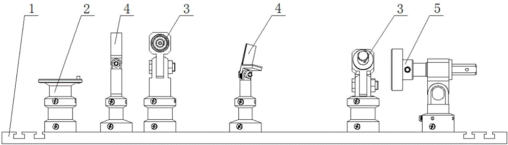
[0026] like figure 1 As shown, a flexible positioning device for pipeline assembly and welding includes a base plate 1, a flange positioning component 2, a pipe joint positioning component 3, a pipe fitting support component 4 and a sleeve type positioning component 5. The method described The blue positioning assembly 2, the pipe joint positioning assembly 3, the pipe fitting support assembly 4 and the sleeve type positioning assembly 5 are all arranged on the foundation base plate 1, and several T-shaped grooves are arranged on the base base plate 1;

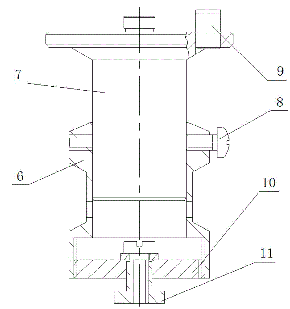
[0027] like figure 2 As shown, the flange positioning assembly 2 includes a first adapter seat 6 and a first adjustment rod 7, a first through hole is provided at the center of the first adapter seat 6, and the first adjustment rod 7 passes through The first through hole is arrange...


PUM


Abstract

The invention relates to a flexible positioning device for assembling and welding pipelines and belongs to the technical field of assembling and welding of pipe parts. A flange positioning assembly, a pipe joint positioning assembly, a pipe fitting bearing assembly and a telescope-feed positioning assembly are all arranged on a foundation plate, and adapting seats of the assemblies are connected with one another through positioning keys and T-shaped grooves. According to the flexible positioning device for assembling and welding the pipelines, by means of matching of the assemblies, accuracy of assembling and welding pipe fittings is improved, shape correction of the pipe fittings during assembling is reduced, manufacture qualities and reliabilities of the pipe fittings are improved, the assemblies can be adjusted, and requirements for assembling and welding the pipe fittings with different sizes and shapes can be well met by adjusting positions and heights of the assemblies when users are confronted with the pipe fittings with different sizes and shapes, so that the applicability of the flexible positioning device is greatly enhanced; the flexible positioning device can be continuously recycled and greatly reduce usage and manufacture costs; defects that medium frames in prior art are low in positioning accuracy, poor in rigidity, easy to deform during using, and long in manufacture period can be overcome.

Description

technical field [0001] The invention belongs to the technical field of assembly and welding of pipe parts, in particular to a flexible positioning device for assembly and welding of pipelines. Background technique [0002] Pipeline components (pipe fittings) play an important role in aero-engines, and are usually welded by branch pipes, pipe joints and flanges. The relative position between them is difficult to express directly with data. [0003] At present, aero-engine ducts still need the help of metal prototypes and jigs to determine the final tube shape, and jigs are still the main tooling for domestic duct manufacturing applications. Since a set of jigs can only be used for one assembly object, it has led to difficulties in the preparation of duct production. In the process, a large number of assembly jigs need to be manufactured; however, the existing jigs have many disadvantages, such as low positioning accuracy, poor rigidity, and easy deformation during use, which...

Claims


Application Information

Patent Timeline
Patent Type & Authority Applications(China)
IPC IPC(8): B23K37/04
CPCB23K37/0426B23K2101/10
Inventor 周京平杨晓东罗敏潘宝山胡金梅
Owner SHENYANG LIMING AERO-ENGINE GROUP CORPORATION
Why Eureka
Try Eureka