

Deep desulfurization method for catalytically cracked gasoline
A technology of catalytic cracking gasoline and deep desulfurization, which is applied in the petroleum industry, processing hydrocarbon oil, refining hydrocarbon oil, etc., and can solve the problems of octane number loss, high octane number loss, and large hydrotreating ratio of full distillate gasoline. Achieve the effect of reducing the loss of octane number and wide applicability
- Summary
- Abstract
- Description
- Claims
- Application Information
AI Technical Summary
Problems solved by technology
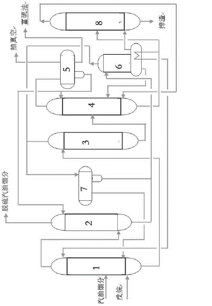
Method used
Image

Examples
Embodiment 1
[0061] According to the above method and process, the gasoline fraction with a boiling range of 40-100°C and a sulfur content of 200-400ppm is used as a raw material, and the process operation conditions shown in the following Table 1 are used to obtain a desulfurization product with a yield of >95%m, desulfurization Product sulfur content <5ppm.
[0062] Table 1
[0063] project
Embodiment 2
[0065] According to the above method and process, the gasoline fraction with a boiling range of 40-100°C and a sulfur content of 600-800ppm is used as a raw material, and the process operation conditions shown in the following Table 2 are used to obtain a desulfurization product with a yield of >95%m, desulfurization Product sulfur content <10ppm.
[0066] Table 2
[0067] project
Embodiment 3
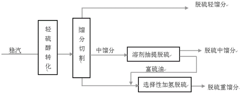
[0069] A general-purpose catalytic cracking gasoline deep desulfurization method, its process is as follows figure 2 As shown, the specific steps are as follows:
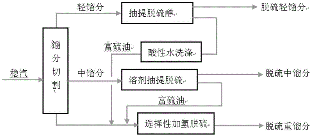
[0070] 1) Cut the stable steam into light gasoline fraction, medium gasoline fraction and heavy gasoline fraction, where the cut point of light gasoline fraction and medium gasoline fraction is 40°C, and the cut point of medium gasoline fraction and heavy gasoline fraction is 100°C;
[0071] 2) The light gasoline fraction obtained in step 1) is subjected to sweetening treatment, such as the method described in ZL200910250279.8 using pure lye to extract the mercaptan sulfur in the C5 fraction into the lye to remove sulfur Desulfurization light distillate and sulfur-rich component H with a content of less than 10ppm; the yield of the low-sulfur light gasoline can generally reach 20-30% (m) of the whole distillate gasoline;
[0072] 3) Treat the medium gasoline fraction obtained in step 1) according to the solvent ex...
PUM
| Property | Measurement | Unit |
|---|---|---|
| boiling point | aaaaa | aaaaa |
| boiling point | aaaaa | aaaaa |
Abstract
Description
Claims
Application Information