Oiling roller for wool top

A technology of oiling rollers and tops, which is applied in the direction of textiles and papermaking, and can solve the problems of splashing, staining machines, and large investment in equipment, and achieves the effects of uniform oiling, easy operation, and simple structure

Inactive Publication Date: 2014-02-05
KUNSHAN CITY SHEN LI MAO FANG CO LTD
View PDF7 Cites 9 Cited by
  • Summary
  • Abstract
  • Description
  • Claims
  • Application Information

AI Technical Summary

Problems solved by technology

But at present, the spraying method commonly used in the wool spinning industry is used to refuel. The oil injector is installed above the wool layer, and the equipment investment is relatively large, and this method of refueling will splash or scatter, waste and crude oil, and stain the machine.

Method used


Image

  • Oiling roller for wool top
  • Oiling roller for wool top

Examples


Embodiment Construction

[0013] The preferred embodiments of the present invention will be described in detail below in conjunction with the accompanying drawings, so that the advantages and features of the present invention can be more easily understood by those skilled in the art, so as to define the protection scope of the present invention more clearly.

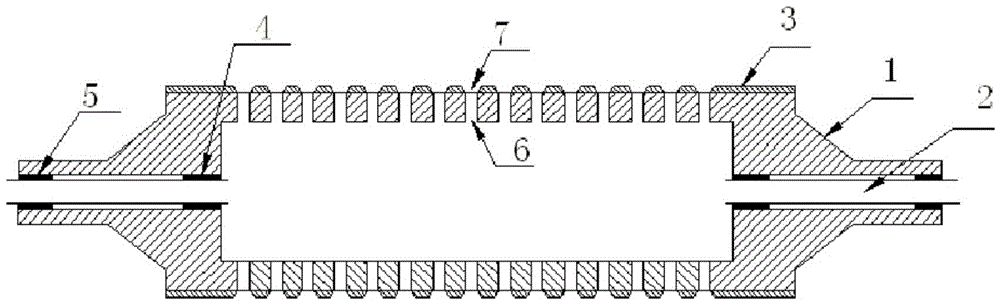
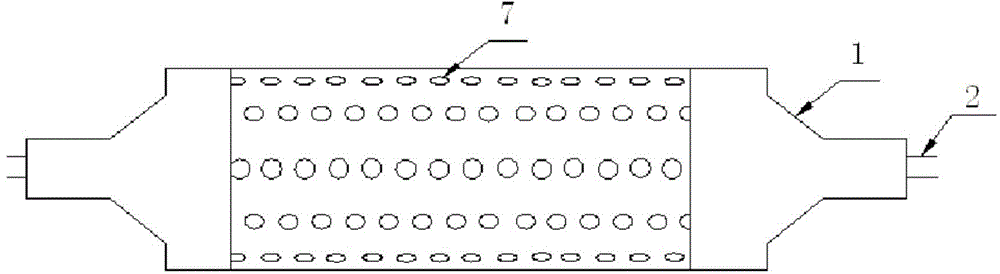
[0014] see figure 1 and figure 2 , the embodiment of the present invention includes:

[0015] An oiling roller for tops, comprising a hollow roller body 1, a plurality of oil outlet holes 6 are arranged on the cylindrical main body part of the hollow roller body 1, and the oil outlet holes 6 are arranged in the longitudinal direction of the cylindrical main part of the hollow roller body 1. Evenly arranged, and two adjacent oil discharge holes 6 are distributed in a staggered manner. The surface of the cylindrical main part of the hollow roller body 1 is provided with a cover tube 3 with holes. The position of each hole 7 on the cover tube 3 co...


PUM


Abstract

The invention discloses an oiling roller for a wool top. The oiling roller comprises a hollow roller body, wherein a plurality of oil outlets are formed in a cylindrical main body part of the hollow roller body; a cover barrel with holes is arranged on the surface of the cylindrical main body part of the hollow roller body; the holes in the cover barrel correspond to the oil outlets; pipelines communicated with an inner cavity of the hollow roller body are arranged at the two ends of the hollow roller body; an oil inlet pipe is arranged in the pipeline at each end. According to the oiling roller, the surface of the wool top can be directly oiled, so that wool oil waste can be avoided; the oil can be uniformly discharged; the oiling roller is simple in structure, convenient to operate and easy to maintain.

Description

technical field [0001] The invention relates to the field of textile equipment, in particular to a top oiling roller. Background technique [0002] In the wool spinning industry, the wool fiber has to undergo repeated carding and drafting in subsequent processing. It not only needs to overcome the friction between itself, but also bear the friction and tension of its running parts. In order to reduce fiber damage, in the mixed sliver Adding a certain amount of wool oil can reduce friction and make the fiber have better softness and toughness, and it is not easy to be broken when stressed. The static electricity generated can reduce the flying hair, prevent the wool net from breaking, reduce the breakage rate, and improve the finished rate and yarn quality. But at present, the spraying method commonly used in the wool spinning industry is used to refuel. The oil injector is installed above the wool layer, and the investment in equipment is relatively large. Moreover, this me...

Claims


Application Information

Patent Timeline
Patent Type & Authority Applications(China)
IPC IPC(8): D01H13/30
Inventor 邹海荣
Owner KUNSHAN CITY SHEN LI MAO FANG CO LTD
Why Eureka
Try Eureka