Method for transition from non-pillar sublevel caving method to upward horizontal cut-and-fill method

A segmented caving method and no bottom pillar technology, which is applied in the direction of filling, earth drilling, safety devices, etc., can solve the problems of complex mining process, increased ore loss rate, and reduced resource utilization rate of the filling method, achieving The effect of reducing the dilution rate, increasing the recovery rate, reducing the loss rate and the dilution rate

Inactive Publication Date: 2014-02-05
WUHAN UNIV OF SCI & TECH
View PDF3 Cites 6 Cited by
  • Summary
  • Abstract
  • Description
  • Claims
  • Application Information

AI Technical Summary

Problems solved by technology

When the backfilling method is used to mine the mining area, a certain thickness of ore is left between the caving area and the mining area. This part of the ore is permanently left underground and cannot be recycled, which reduces the utilization rate of resources and increases the loss rate of ore. , and the filling process is complex

Method used


Image

  • Method for transition from non-pillar sublevel caving method to upward horizontal cut-and-fill method

Examples


Embodiment 1

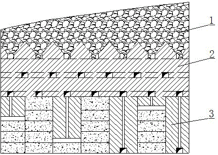
[0021] It is a method of transitioning upward from the sub-level caving method without pillars to the horizontal layered filling method. The method as figure 1 As shown, in a stage immediately below the caving area 1 of the mining area, the stage is divided into an isolation zone 2 and a mining zone 3, the upper part of the stage is the isolation zone 2, and the lower part of the stage is the mining zone 3.

[0022] The mining sequence of the stages is that the mining area is mined first, and then the isolation zone 2 is mined.

[0023] The mining method in the said stage is that the mining area 3 adopts the upward horizontal layered filling method, and the isolation zone 2 adopts the segmental caving method without bottom pillars.

[0024] The thickness of the isolation zone 2 is 1 time of the subsection height of the non-bottom column subsection caving method.

[0025] The post-mining isolation zone 2 refers to mining the isolation zone 2 after the filling body in the mini...

Embodiment 2

[0027] It is a method of transitioning upward from the sub-level caving method without pillars to the horizontal layered filling method. The method as figure 1 As shown, in a stage immediately below the caving area 1 of the mining area, the stage is divided into an isolation zone 2 and a mining zone 3, the upper part of the stage is the isolation zone 2, and the lower part of the stage is the mining zone 3.

[0028] The mining sequence of the stages is that the mining area is mined first, and then the isolation zone 2 is mined.

[0029] The mining method in the said stage is that the mining area 3 adopts the upward horizontal layered filling method, and the isolation zone 2 adopts the segmental caving method without bottom pillars.

[0030] The thickness of the isolation zone 2 is twice the subsection height of the non-bottom column subsection caving method.

[0031] The post-mining isolation zone 2 refers to mining the isolation zone 2 after the filling body in the mining a...


PUM


Abstract

The invention relates to a method for transition from a non-pillar sublevel caving method to an upward horizontal cut-and-fill method. The technical scheme is as follows: in a section close to and below a caved area (1) of a mining area, the section is divided into an isolation zone (2) and a recovery area (3), the upper part of the section is the isolation zone (2), and the lower part of the section is the recovery area (3). The section is exploited in such a sequence that the recovery area is exploited before the isolation zone (2) is exploited. An exploitation method of the section is as follows: the upward horizontal cut-and-fill method is adopted for the recovery area (3), and the non-pillar sublevel caving method is adopted for the isolation zone (2). The thickness of the isolation zone (2) is one or two times of the sublevel height of the non-pillar sublevel caving method. The isolation zone (2) is exploited after final setting of a filling body of the recovery area (3). The method has the characteristics that the loss ratio of ore can be reduced, the dilution rate can be reduced, the surface vegetation and the ecological environment can be protected, atmospheric conditions of a stope can be improved, and the recovery is simple.

Description

technical field [0001] The invention belongs to the technical field of mining. In particular, it relates to a method for transitioning upward from the bottom-less column sub-caving method to the horizontal layered filling method. Background technique [0002] In the last century, more than 90% of large and medium-sized underground mines in my country were mined by the highly efficient and low-cost pillarless sub-level caving method. In the segmental caving method without pillars, as the mining face advances, the surrounding rock caving fills the goaf at the same time, so as to realize the management and control of ground pressure. When the sub-level caving method without pillars is used, with the collapse of surrounding rocks and ores, it will cause different degrees of subsidence or subsidence on the surface, seriously destroying the vegetation and ecological environment on the surface; The loss and dilution increase, and the ventilation conditions of the stope are poor. ...

Claims


Application Information

Patent Timeline
Patent Type & Authority Applications(China)
IPC IPC(8): E21F15/00
Inventor 刘艳章邓磊王其飞叶义成柯丽华张丙涛张群赵卫石志军刘洋
Owner WUHAN UNIV OF SCI & TECH
Why Eureka
Try Eureka