
LED module

A technology of LED modules and cooling blocks, which is applied in the cooling/heating devices of lighting devices, lighting and heating equipment, electrical components, etc., and can solve the problem that the shape and power cannot be adjusted, and the brightness of LED lighting cannot be greatly increased. increase and other issues, to achieve the effect of improving LED constant current driving effect, good protection performance, and reducing power supply requirements

Inactive Publication Date: 2014-02-05
浦江浦发科技有限公司
View PDF6 Cites 1 Cited by
  • Summary
  • Abstract
  • Description
  • Claims
  • Application Information

AI Technical Summary

Problems solved by technology

The biggest disadvantage of existing LED modules is that they cannot be changed. Once the product is formed, its shape and power cannot be adjusted. The brightness can only be adjusted through the brightness adjustment module in its circuit, that is, the brightness cannot be greatly increased. The need to increase brightness can only be achieved by increasing the number of LED lights. Multiple LED lights are not connected separately, or are electrically connected together through exposed wires, which cannot be used as a unified whole.
In addition, most of the current LED market uses low-voltage LEDs. With the maturity of AC LED and DC high-voltage LED technologies, AC LED and DC high-voltage LED technologies will be widely used. Different types of LEDs have different driving voltage modes and LED arrays. The layout method is different. If you need to make a different PCB board and a different lens cover every time you change a type of LED, it will not only be troublesome, but will also cause a waste of materials.

Method used


Image

  • LED module
  • LED module
  • LED module

Examples


Embodiment 1

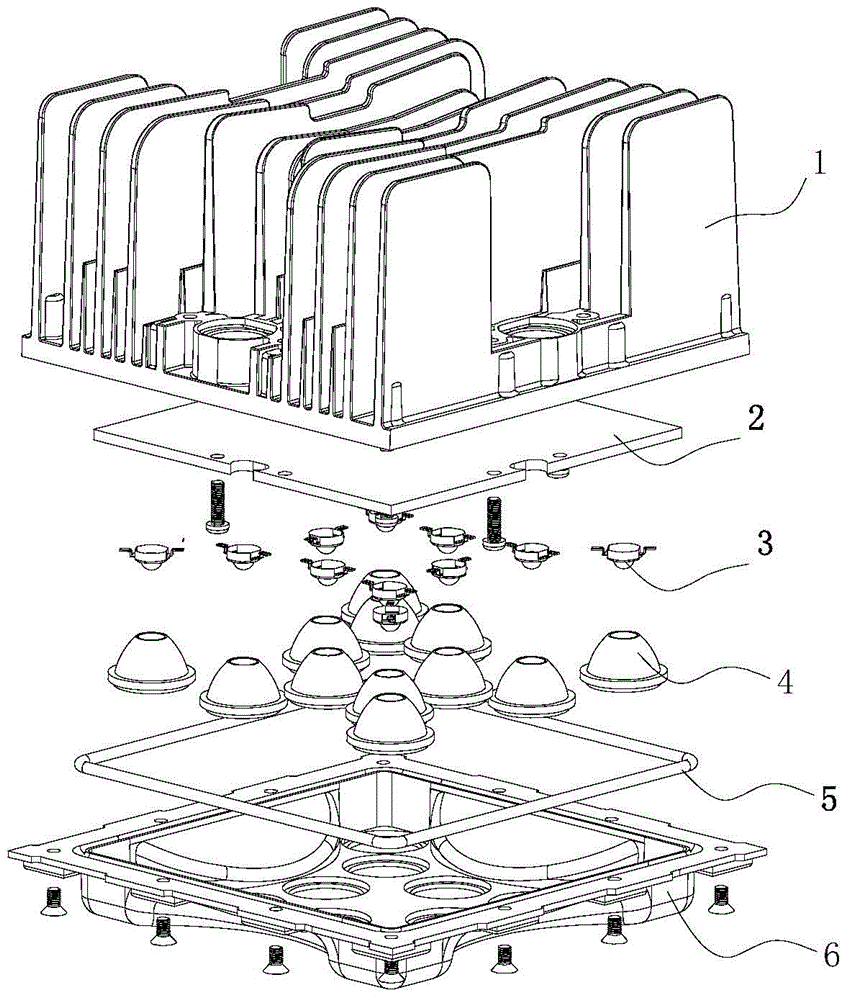
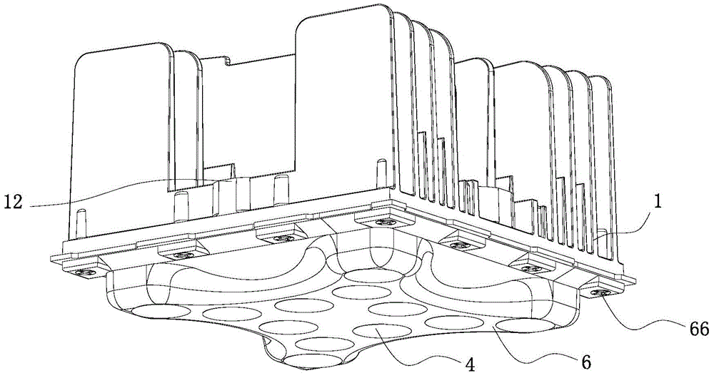
[0027] like Figure 1-7 The LED module shown mainly includes LED 3 , PCB board 2 , lens 4 , lens mask 6 and cooling block 1 .

[0028] LED3 is installed on the PCB board 2, specifically, the bottom of LED3 is integrally connected to the PCB board 2, so as to reduce the power supply requirements and reduce the unit size, which not only effectively reduces the requirements for power supply performance, but also compresses the volume space. The IC chip 22 on the PCB board 2 controls the working current and working heat of the LED through pulse width modulation, and adjusts the voltage regulation and constant current by changing the duty cycle.

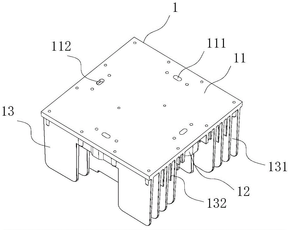
[0029] The heat dissipation block 1 is an integral aluminum heat dissipation block, and the heat dissipation block 1 is composed of a fixed panel 11 and a connection assembly 12 and a heat dissipation plate 13 thereon. The PCB board 2 is fixed on the bottom surface of the fixed panel 11, the bottom of the cooling plate 13 and the connect...

Embodiment 2

[0042] like Figure 8 The other structure of the LED module shown is the same as that of the LED module in Embodiment 1, and some structures and functions are added on the basis of Embodiment 1. Specifically, the heat sink plate 13 in the middle is provided with a screw hole connected with it The mounting column 133 has an opening of the screw hole upwards, and a connecting plate 134 is installed on the mounting column 133. The mounting screws pass through the connecting plate 134 and are fixed on the mounting column 133. The connecting plate 134 can be used for installing and fixing the entire LED module. An electrical connector 124 is provided on the connecting assembly 12 for docking with the LED module, and the electrical connecting head 124 is treated with IP protection, that is, sealing and waterproof gaskets are provided on the upper and lower sides of the electrical connecting head 124, and in addition, on the connecting assembly 12 that is not used for docking , plug ...

Embodiment 3

[0044] like Figure 9 The other structures of the LED module shown are the same as that of the LED module in Embodiment 1, and some structures and functions are added on the basis of Embodiment 1. Specifically, a mounting connection plate 123 is set on the connection assembly 12, and the screws pass through the mounting connection The board 123 is fixed in the connecting hole 125, and the connecting board 123 is installed with a hole. The connection assembly 12 does not have a docking function but an installation function, and can be used for installation and fixing of the entire LED module by installing the connection plate 123 . In addition, the heat sink plate 13 in the middle is provided with a mounting column 133 with a screw hole integrally connected with it, and the opening of the screw hole is upward, and the mounting column 133 can be used for fixing the LED module in other ways. An electrical connector 124 is provided on the connection assembly 12 for docking with t...


PUM


Abstract

The invention relates to the field of LED lights, in particular to an LED module comprising an LED, a PCB, a lens, a lens cover and a radiating block. The LED is installed on the PCB which is fixed on the radiating block. The lens is hermetically installed on the lens cover which is fixed on the radiating block. The radiating block of aluminum comprises a fixed panel, a connection set and a radiating plate, wherein the connection set and the radiating plate are arranged on the fixed panel and both connected to the top of the fixed panel. The PCB is fixed at the bottom of the fixed panel. The connection set is provided with an electrical connection. The PCB is provided with a power connection which positionally matches the electrical connection of the connection set and which is communicated with the electrical connection. The fixed panel is provided with a wire passage between the electrical connection and the power connection. The LED module is novel in structure, optionally combinable, well water proof and suitable for outdoor uses.

Description

technical field [0001] The invention relates to the field of LED lighting fixtures. Background technique [0002] LED lighting has been widely used because of its advantages of energy saving and environmental protection. The LED module is the most important component in the LED lamp. The biggest disadvantage of existing LED modules is that they cannot be changed. Once the product is formed, its shape and power cannot be adjusted. The brightness can only be adjusted through the brightness adjustment module in its circuit, that is, the brightness cannot be greatly increased. The need to increase brightness can only be achieved by increasing the number of LED lighting lamps. Multiple LED lighting lamps are separated and not connected, or are electrically connected together through exposed wires, which cannot be used as a unified whole. In addition, most of the current LED market uses low-voltage LEDs. With the maturity of AC LED and DC high-voltage LED technologies, AC LED an...

Claims


Application Information

Patent Timeline
IPC IPC(8): F21S2/00F21V17/10F21V29/00F21V23/00F21Y101/02F21K9/20F21V29/74F21Y115/10H05B44/00
CPCF21V3/00F21V5/048F21V19/001F21V23/06F21V29/70F21V29/71F21V31/005H05B45/10H05B45/00Y02B20/30
Inventor 王元成王丽娜
Owner 浦江浦发科技有限公司
Learn More