Slant finned tube

A finned tube and fin technology, which is applied in the field of heat exchange equipment, can solve the problems that the heat exchanger fails to achieve the design effect, affects the heat exchange efficiency, and is difficult to remove, and achieves long-term stable and effective heat exchange effect and extended use. Long life and good anti-scaling effect

Active Publication Date: 2014-02-05
THE CHALLENGE PETROCHEM MACHINERY CORP
View PDF6 Cites 7 Cited by
  • Summary
  • Abstract
  • Description
  • Claims
  • Application Information

AI Technical Summary

Problems solved by technology

[0007] With the development of device technology, there are more and more occasions where finned tubes are installed vertically. Since the traditional fins are basically installed perpendicular to the surface of the base tube, when the finned tube heat exchanger is installed vertically, it is basically vertical. The plane of the fins on the surface of the base tube becomes close to the horizontal plane. During the long-term operation of this structure, the dust in the flue gas outside the tube or the dust in the air accumulates on the plane of the fins, forming dirt, which is difficult to remove. , a thermal resistance is formed between the medium inside the tube and the flue gas outside the tube, which affects the heat transfer efficiency
The above problems occur when the finned tubes in the finned tube heat exchanger are installed vertically. If the traditional horizontal installation mode is used, the above problems do not exist, or the above problems are very small, and it is easy to wash them with a soot blower or jet water However, for the vertical installation mode, there will be a big problem that needs to be solved urgently
[0008] In summary, when the finned tube is installed and used vertically, the fin structure design of the finned tube is the most important and critical link to avoid dust accumulation and fouling. If the fin structure is not innovated to prevent the existing Problems often cause the heat exchanger to fail to achieve the design effect

Method used


Image

  • Slant finned tube
  • Slant finned tube
  • Slant finned tube

Examples


Embodiment 1

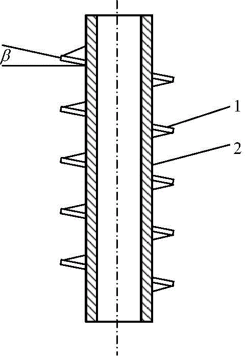
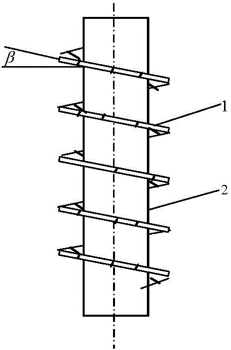
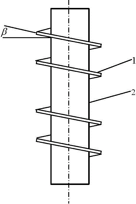
[0038] One of the specific implementations of an oblique finned tube of the present application, see figure 1 As shown, it includes a base pipe 2 and several fin bodies 1 arranged on the base pipe 2, wherein the fin body 1 includes an inclined surface and a fin center hole arranged inside the inclined surface, so The central hole of the fin is closely connected with the outer wall of the base tube 2, and the plurality of fin bodies 1 are arranged continuously around the outer wall of the base tube 2 along the axial direction of the base tube 2 (such as figure 2 shown) or a discontinuous surround setting (such as image 3 shown). In the discontinuous surrounding arrangement, the distance between each fin body 1 can be set at equal or unequal lengths, depending on the specific operating conditions. Usually, discontinuous surroundings with unequal lengths are more conducive to improving the heat transfer efficiency of finned tubes . This structure makes the flue gas ash or a...

Embodiment 2

[0044] The second specific embodiment of an oblique finned tube of the present application, see Figure 4As shown, it includes a base pipe 2 and several fin bodies 1 arranged on the base pipe 2, wherein the fin body 1 includes an umbrella body and a fin center hole arranged in the middle of the umbrella body, so The fin body is tightly fit on the outer wall surface of the base pipe 2 through the central hole of the fin. The fin bodies 1 are independently inserted into the base pipe from the pipe end for assembly and fitting. This structure makes the flue gas ash or air dust slide down from the inclined umbrella surface of the finned umbrella body and cannot accumulate, so that the anti-fouling effect is good, so that the heat exchange effect can be kept stable and effective for a long time, and it can reduce or avoid the dust caused by the removal of the heat exchanger. The operation and maintenance of frequent shutdown and blowing fin ash, but also has the characteristics of...

Embodiment 3

[0048] The third specific embodiment of an oblique finned tube of the present application, see Figure 7 and Figure 8 As shown, it includes a base pipe 2 and several fin bodies 1 arranged on the base pipe 2, wherein the fin body 1 includes inclined annular fins and fins arranged at the ends of the inclined annular fins. Flange 8 , the inclined annular fin is sheathed on the outer wall surface of the base pipe 2 through its inner ring, and is closely connected with the outer wall surface of the base pipe 2 . Flange 8 can be arranged upwards, also can be arranged downwards. The annular shape of the inclined annular fins can be a ring shape with a trapezoidal cross-section, or a ring shape with a triangular cross-section. The above-mentioned structure is more conducive to the sliding of smoke ash or air dust.

[0049] This structure makes the flue gas ash or air dust slide down from the inclined umbrella surface of the finned umbrella body and cannot accumulate, so that the an...


PUM


Abstract

The invention discloses a slant finned tube. A plurality of fin bodies comprise slant planes and fin center holes formed in the inner sides of the slant planes, and the plurality of fin bodies are inclined to the outer wall surface of a base tube and continuously or intermittently arranged in a surrounding manner in the axial direction of the base tube; or the fin bodies comprise umbrella-shaped bodies and fin center holes formed in the middles of the umbrella-shaped bodies, and the outer wall surface of the base tube is tightly sleeved with the fin bodies through the fin center holes; or the fin bodies comprise slant ring-surface fins and flanging arranged at the end parts of the slant ring-surface fins, the outer wall surface of the base tube is sleeved with the slant ring-surface fins through inner rings, and the slant ring-surface fins are tightly connected with the outer wall surface of the base tube. After the slant finned tube is used, smoke ash or air dust can slide from the slant planes of the fins and cannot be accumulated, so that the scale prevention effect is good, long-term stable and effective heat transfer effect is maintained, and conditions of frequent shutdown caused by dust removal of the heat exchanger and operational maintenance for blowing fin ash can be reduced or avoided; and meanwhile, the slant finned tube has the characteristics that the structure is simple and the service life of the finned tube is prolonged.

Description

Technical field [0001] This application involves the technology fields of heat exchanging equipment in industries such as air conditioning, chemical industry, petrochemical, power energy, steel smelting, etc., especially an oblique wing -winged tube. Background technique [0002] The heating device of the spiral fin tube includes a variety of heating furnaces, wing tube heater, and air -cooler. It is one of the widely used heat exchangers. Its design and manufacturing process are mature, high safety, and in the heat exchange equipment.It is a key energy -saving equipment.People use the spiral fin tube to achieve certain results in the enhancement of heat exchangers. Therefore, it is satisfied with existing results. For a long time, the structure of the spiral wing tube has not been further improved. [0003] (1) Structural function of traditional spiral -wing tube. [0004] At present, the spiral -winged tubes used in the heat exchange of domestic petrochemicals and other devices...

Claims


Application Information

Patent Timeline
Patent Type & Authority Applications(China)
IPC IPC(8): F28F1/36F28F1/34
Inventor 陈孙艺
Owner THE CHALLENGE PETROCHEM MACHINERY CORP
Why Eureka
Try Eureka