
In-situ real-time monitoring system for strain in gauge length of fatigue specimens in high temperature and high pressure water

A real-time monitoring system, high-temperature and high-pressure water technology, applied in the direction of electric/magnetic solid deformation measurement, application of stable tension/pressure test material strength, electromagnetic measurement device, etc., can solve the problem of unable to monitor the gauge length section of fatigue samples in situ Insufficient measurement accuracy of displacement and strain, etc., to achieve the effect of ingenious design, simple and convenient operation, and improved accuracy

Active Publication Date: 2016-01-13
INST OF METAL RESEARCH - CHINESE ACAD OF SCI
View PDF1 Cites 0 Cited by
  • Summary
  • Abstract
  • Description
  • Claims
  • Application Information

AI Technical Summary

Problems solved by technology

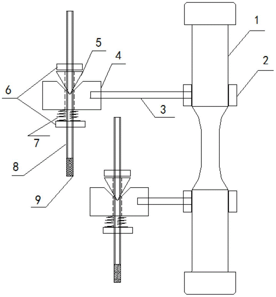
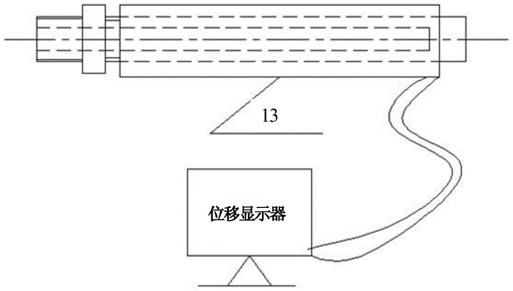
[0004] The purpose of the present invention is to provide an LVDT system capable of in-situ real-time and accurate monitoring of the gauge length strain of fatigue samples in high-temperature and high-pressure water, so as to solve the problem of in-situ monitoring of the gauge-length displacement of fatigue samples in the existing high-temperature and high-pressure water corrosion fatigue test process , the problem of insufficient strain measurement accuracy

Method used


Image

  • In-situ real-time monitoring system for strain in gauge length of fatigue specimens in high temperature and high pressure water
  • In-situ real-time monitoring system for strain in gauge length of fatigue specimens in high temperature and high pressure water
  • In-situ real-time monitoring system for strain in gauge length of fatigue specimens in high temperature and high pressure water

Examples


Embodiment

[0045] In the accuracy correction test, a standard rod-shaped fatigue sample with a diameter of 8mm in the gauge section, a length of 16mm in the gauge section, and a diameter of 16mm in both ends of the gauge section is used. Install a linear variable differential pressure variable displacement sensor system for in-situ real-time monitoring of strain in the gauge section of fatigue samples in high-temperature and high-pressure water. The displacement of the fatigue machine is selected as 0-0.4mm, and the test is repeated three times at each point.

[0046] Figure 7(a) It is a comparison of the monitoring data of the fatigue machine displacement sensor, the linear variable differential pressure variable displacement sensor system, and the strain gauge during the unidirectional stretching process. It can be seen that the three are approximately linear correspondences; Figure 7(b) It is the relationship between the monitoring data of the linear variable differential pressure ...


PUM


Abstract

The invention relates to the field of corrosion fatigue tests, in particular to a normal position real-time monitoring system for high-temperature and high-pressure water fatigue testing specimen scale distance section strain and an application method thereof. A semi-circular Ohm clamp clamps the two ends of a fatigue testing specimen scale distance, the Ohm clamp and a V-shaped opening square block are connected through a connecting screw rod, one end of a non-magnetic connecting screw rod is connected with an induction iron core of an LVDT, and the other end of the non-magnetic connecting screw rod penetrates through the V-shaped opening square block. Two nuts are screwed on the non-magnetic connecting screw rod, a compression spring is placed on the inner sides of the nuts, a tetrahedron block with a through hole is placed at the other end of the non-magnetic connecting screw rod, and the V-shaped opening square block and the tetrahedron block with the through hole are pressed tightly by the nuts to fix the non-magnetic connecting screw rod. The outer end of a high-pressure autoclave cover is connected with a spacer bush through a thread in a hard sealing mode, and a water jacket is arranged outside the spacer bush. The LVDT is connected with the lower end of the spacer bush through a thread and is connected with a displacement displayer. Therefore, by means of the matched installation, the position of the induction iron core is adjusted, zero clearing is carried out, and the strain of a fatigue testing specimen scale distance in the high-temperature and high-pressure water can be motored in a real-time and normal position mode.

Description

technical field [0001] The invention relates to the field of corrosion fatigue tests, in particular to a linear variable differential pressure transformation displacement sensor (LVDT, LinearVariableDifferentialTransformer) system for in-situ real-time monitoring of strain in the gauge section of fatigue samples in high-temperature and high-pressure water, which is used for metal rod-shaped fatigue samples Low cycle fatigue test in high temperature and high pressure water. Background technique [0002] The corrosion fatigue behavior of nuclear power structural materials in high-temperature and high-pressure water is the focus of safety design, management and life assessment of nuclear power plants. Many operating experiences and studies have shown that high-temperature and high-pressure water corrosion fatigue is one of the potential forms of failure of nuclear power structural materials. Hotspots for Stress Boundary Design Fatigue Curve Improvement. Internationally (the Un...

Claims


Application Information

Patent Timeline
Patent Type & Authority Patents(China)
IPC IPC(8): G01B7/16G01N3/18
Inventor 谭季波吴欣强韩恩厚王翔
Owner INST OF METAL RESEARCH - CHINESE ACAD OF SCI
Learn More