Accurate temperature measuring system for high-voltage switch cabinet busbar

A technology for high-voltage switchgear and accurate temperature measurement, which is applied in the field of temperature measurement systems, can solve problems such as the inability to accurately detect the temperature of busbars with protective sleeves, and achieve the effects of easy installation, easy and safe installation, and low price

Inactive Publication Date: 2014-02-05
STATE GRID CORP OF CHINA +2
View PDF3 Cites 3 Cited by
  • Summary
  • Abstract
  • Description
  • Claims
  • Application Information

AI Technical Summary

Problems solved by technology

[0004] In order to solve the problem that the existing method of monitoring the contact temperature in the high-voltage switch cabinet using an infrared temperature measuring gun cannot acc...

Method used


Image

  • Accurate temperature measuring system for high-voltage switch cabinet busbar
  • Accurate temperature measuring system for high-voltage switch cabinet busbar
  • Accurate temperature measuring system for high-voltage switch cabinet busbar

Examples


specific Embodiment approach 1

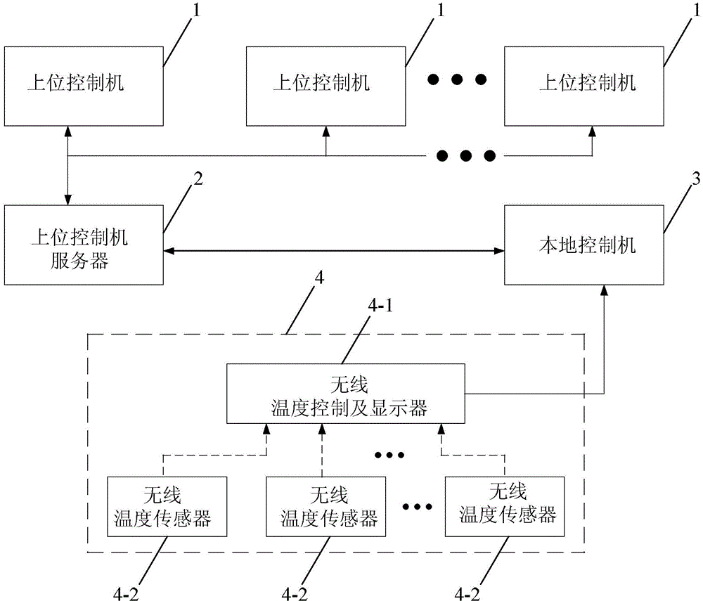
[0013] Specific implementation mode one: combine figure 1 Describe this embodiment, the high-voltage switchgear busbar accurate temperature measurement system described in this embodiment, which includes N upper controllers 1, upper controller servers 2, local controllers 3 and wireless temperature measurement components 4; N is a natural number; The upper control data signal output and input ends of the upper control machine server 2 are connected with the upper control data signal output and input ends of each upper control machine 1 at the same time; the temperature data signal output and input ends of the local control machine 3 are connected with the temperature The data signal output and input terminals are connected; the local temperature data output terminal of the wireless temperature measurement component 4 is connected with the local temperature data input terminal of the local control machine 3, and the temperature collection terminal of the wireless temperature mea...

specific Embodiment approach 2

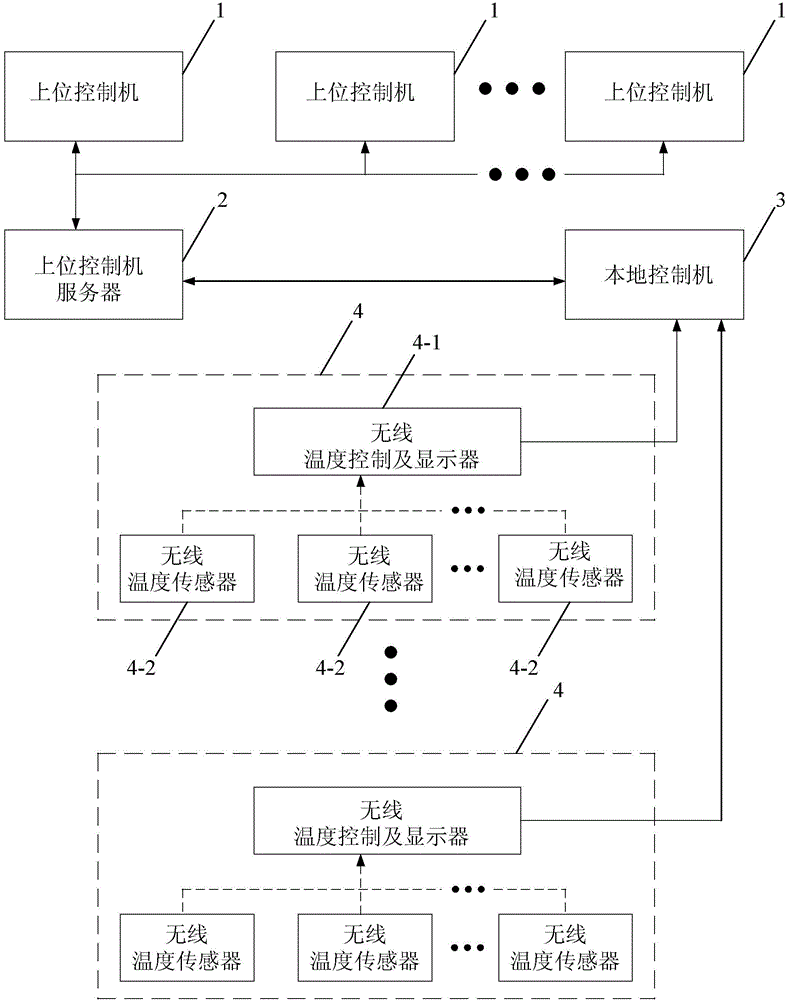
[0014] Specific implementation mode two: combination figure 2 Describe this embodiment, the difference between this embodiment and the specific embodiment is that it also includes M wireless temperature measurement components 4; the structure and composition of the M wireless temperature measurement components 4 are the same; each of the wireless temperature measurement The local end temperature data output end of the component 4 is connected with a local end temperature data input end of the local control machine 3 respectively; The server-side temperature data input port is connected. Other compositions and connection methods are the same as those in Embodiment 1.

specific Embodiment approach 3

[0015] Specific implementation mode three: combination figure 1 or figure 2 Describe this embodiment, the difference between this embodiment and the second embodiment is that the wireless temperature measurement component 4 includes a wireless temperature control and display 4-1 and L wireless temperature sensors 4-2; the wireless temperature control and display 4-1 The local end temperature data output end of the wireless temperature measurement assembly 4 is the local end temperature data output end of the wireless temperature measurement component 4; the server end temperature data output end of the wireless temperature control and display 4-1 is the server end temperature of the wireless temperature measurement assembly 4 Data output terminals; the L wireless temperature data input terminals of the wireless temperature control and display 4-1 are connected to the wireless temperature data output terminals of a wireless temperature sensor 4-2 correspondingly. Other compos...


PUM


Abstract

The invention discloses an accurate temperature measuring system for a high-voltage switch cabinet busbar, and relates to temperature measuring systems. The accurate temperature measuring system for the high-voltage switch cabinet busbar is put forward to solve the problem that the temperature of a busbar with a protective cover cannot be accurately detected through the method that in the prior art, the temperature of an inner contact of a high-voltage switch cabinet is monitored through an infrared temperature measuring gun. The upper control data signal output end and the upper control data signal input end of an upper controller server are connected with the upper control data signal output end and the upper control data signal input end of each upper controller at the same time. The temperature data signal output end and the temperature data signal input end of a local controller are connected with the temperature data signal output end and the temperature data signal input end of the upper controller server. The local terminal temperature data output end of a wireless temperature measuring assembly is connected with the local terminal temperature data input end of the local controller. The temperature collecting end of the wireless temperature measuring assembly collects the temperature of the high-voltage switch cabinet busbar. The accurate temperature measuring system for the high-voltage switch cabinet busbar can be widely applied to measuring the temperature of various high-voltage switch cabinets.

Description

technical field [0001] The invention relates to a temperature measuring system, in particular to a busbar temperature measuring system. Background technique [0002] With the development of electric power technology, high-voltage and ultra-high-voltage distribution networks are increasingly appearing in major power grids. As important electrical equipment, high-voltage switchgear, The resistance increases, causing overheating, and serious fire accidents. In recent years, many switchgear overheating accidents have occurred in power plants and substations, causing fires and large-scale power outages. Solving the problem of switchgear overheating is the key to preventing such accidents. [0003] At present, monitoring the contact temperature in the switchgear can effectively prevent accidents in the switchgear, but due to the high-voltage structure in the switchgear, manual inspection and temperature measurement cannot be carried out. The temperature cannot be measured from t...

Claims


Application Information

Patent Timeline
IPC IPC(8): G01K13/00
Inventor 周春利刘淑杰刘谦李建阁赵双马兴明
Owner STATE GRID CORP OF CHINA
Why Eureka
Try Eureka