Milling stability domain prediction method under multi-modal coupling

A forecasting method and multi-modal technology, which can be used in forecasting, data processing applications, computing, etc., and can solve problems such as low efficiency

Active Publication Date: 2014-02-05
NORTHWESTERN POLYTECHNICAL UNIV
View PDF3 Cites 24 Cited by
  • Summary
  • Abstract
  • Description
  • Claims
  • Application Information

AI Technical Summary

Problems solved by technology

[0006] In order to overcome the inefficiency of the existing milling stable domain prediction method, the present invention provides a milling stable domain prediction method under multi-modal coupling

Method used


Image

  • Milling stability domain prediction method under multi-modal coupling
  • Milling stability domain prediction method under multi-modal coupling
  • Milling stability domain prediction method under multi-modal coupling

Examples


Embodiment Construction

[0034] The specific steps of the milling stable region prediction method under multi-modal coupling in the present invention are as follows.

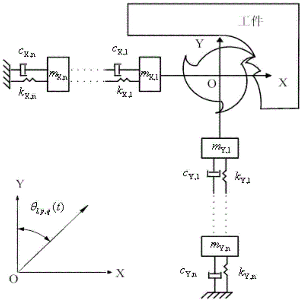
[0035] 1) Install a milling cutter with a radius of 12mm, a helix angle of 30°, and a number of teeth N of 3 on the tool holder and then on the machine tool spindle system, and then use the standard impact test to test the modal of the milling cutter-tool holder-machine tool spindle system Parameters, the modal parameters of each order obtained from the test, as shown in the following table:

[0036] Table 1. Modal parameters

[0037]

[0038] 2) Combine the modal parameters in the X direction and Y direction measured in step 1), that is, the first-order modal parameters in the X direction and the first-order modal parameters in the Y direction are combined into a group and recorded as a model State 1; Similarly, the second-order modal parameters in the X direction and the second-order mode in the Y direction are combined into a group...


PUM


Abstract

The invention discloses a milling stability domain prediction method under multi-modal coupling to solve a technical problem that the efficiency of an existing milling stability domain prediction method is low. The technical scheme is that firstly the transmission function of a process system is determined through a modal test experiment, then modal parameters are extracted from the transmission function and two orthogonal direction modal parameters are paired and combined, a milling test is carried out to calibrate a milling force coefficient, based on the milling force coefficient and each scale of modal parameters, an improved semi discrete method is employed to obtain a stability lobe diagram under each scale of modals, and finally lobe diagrams under obtained from each scale of modals are drawn in a same coordinate system to obtain a stable domain under multi modal coupling. Through a test, when a cutting cycle is divided into 40 sections, 80 sections and 120 sections, compared with a background technology method, the method can save time for 4949.6 seconds, 74200.4 seconds and 344699.5 seconds, and the efficiency is increased by 85.9%, 92% and 88.5%.

Description

technical field [0001] The invention relates to a milling stable region prediction method, in particular to a milling stable region prediction method under multi-modal coupling. Background technique [0002] refer to Figure 1-2 . Milling is one of the most commonly used metal forming processes, and it is widely used in the production and manufacture of various molds, auto parts and aerospace parts. Regenerative chatter caused by unreasonable selection of cutting parameters during milling will seriously affect machining accuracy and tool life, and even lead to premature failure of the machine tool. In order to select the cutting parameters reasonably and avoid the occurrence of chatter, it is necessary to establish an effective stable region prediction method. Considering the complexity of the actual process system, in order to accurately characterize its dynamic behavior, it is necessary to establish a multi-degree-of-freedom model to predict the stability domain of the m...

Claims


Application Information

Patent Timeline
Patent Type & Authority Applications(China)
IPC IPC(8): G06Q10/04
Inventor 万敏马颖超张卫红杨昀
Owner NORTHWESTERN POLYTECHNICAL UNIV
Why Eureka
Try Eureka