Coil-winding wire carding machine

A wire and coil technology, applied in the field of coil winding auxiliary tools in power systems, can solve the problems of slow construction speed and unguaranteed coil winding quality, and achieve the effect of flexible and convenient use

Active Publication Date: 2014-02-05
STATE GRID CORP OF CHINA +1
View PDF6 Cites 2 Cited by
  • Summary
  • Abstract
  • Description
  • Claims
  • Application Information

AI Technical Summary

Problems solved by technology

[0003] Aiming at the problems existing in the above-mentioned prior art, the present invention provides a wire carding device for coil winding, which solves the problems in the prior art that the coil winding quality cannot be guaranteed and the construction speed is slow

Method used


Image

  • Coil-winding wire carding machine

Examples


Embodiment 1

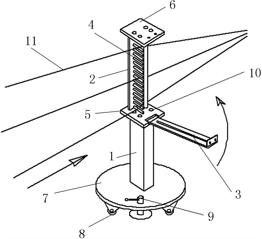
[0023] Such as figure 1 As shown, the bottom of the body 1 is provided with a reinforced base 7, and the reinforced base 7 is provided with a direction adjustment device. The structure of the direction adjusting device is as follows: a steering wheel 8 is arranged under the base 7, and two positioning discs 9 are arranged on the base; the two positioning discs are symmetrically arranged on both sides of the body 1. The two sides of the bottom plate 5 of the device body are respectively provided with splints I 2 and splints II 3, the splint I and the base plate are fixedly connected, and the splint II and the base plate are connected through a shaft rotation; a guide rod 4 is arranged between the splint I and the splint II, One end of the guide rod is fixed on the splint I, and the other end is flexibly connected to the splint II; the number of guide rods is 25 laterally; the gap between the guide rods is greater than the diameter of the wire 11.

[0024] The bottom plate is p...

Embodiment 2

[0026] The structure of the direction adjusting device is that a universal wheel is arranged under the base, and a fixed card seat is arranged on the universal wheel. Both the clamping plate I, the clamping plate II and the base plate are connected through shaft rotation. The two ends of the guide rod are respectively movably connected to the splint I and the splint II; other structures are the same as in the first embodiment.

[0027] When in use, open the splint, put multiple wires between the guide rods one by one, close the splint, adjust the direction, and unscrew the positioning plate. When the coil is wound, the wire flows through the gaps of the rollers to ensure time-saving and labor-saving, so as to solve the problems of low winding quality and slow construction speed of transformer coils, save labor costs, and reduce labor intensity. Coil winding process level The improvement ensures the quality of the product, improves the work efficiency, and saves 3 construction...


PUM


Abstract

The invention relates to a coil-winding wire carding machine which comprises guide rods, rollers, a machine body, clamping plates and a positioning disk, wherein the clamping plate I and the clamping plate II are respectively arranged on two sides of a base plate of the machine body; the guide rods are arranged between the clamping plate I and the clamping plate II. During use, the clamping plates are opened, and a plurality of wires are put between every two guide rods in sequence; then the clamping plates are closed, and the positioning disk is screwed down. During coil winding, the wires flow through gaps of the rollers, so that the time and the labor are saved, and the wires cannot fall off; therefore, the problems of low winding quality of transformer coils and low construction speed are solved; the labor cost is saved, and the labor intensity is reduced.

Description

technical field [0001] The invention relates to an auxiliary tool for coil winding in a power system, in particular to a wire comber for coil winding. Background technique [0002] When winding a large-capacity transformer, the number of wires in the low-voltage coil can be as many as 24 or more, and the wires that are put down from the wire reel to the hands of the winding personnel need to be arranged and wound into coils, often requiring 3 people to specialize The quality of coil winding cannot be guaranteed, and the construction speed is slow, making it difficult to meet the progress requirements of the construction period. Contents of the invention [0003] The present invention aims at the problems existing in the above-mentioned prior art, and provides a wire carding device for coil winding, which solves the problems in the prior art that the coil winding quality cannot be guaranteed and the construction speed is slow. [0004] Technical scheme of the present inven...

Claims


Application Information

Patent Timeline
Patent Type & Authority Applications(China)
IPC IPC(8): H01F41/06H01F41/096
Inventor 刘增梁继利宋宏斌赵本利李春明胡本成王刚张宁
Owner STATE GRID CORP OF CHINA
Why Eureka
Try Eureka