Heat dissipation structure and electronic device

A technology of heat dissipation structure and sub-air duct, applied in the direction of cooling/ventilation/heating transformation, can solve the problem of uneven current flow between two power units, affecting the performance of photovoltaic inverters, etc., to eliminate the phenomenon of thermal cascade, current The effect of equalizing flow and improving performance

Active Publication Date: 2016-03-30
HUAWEI DIGITAL POWER TECH CO LTD
View PDF7 Cites 0 Cited by
  • Summary
  • Abstract
  • Description
  • Claims
  • Application Information

AI Technical Summary

Problems solved by technology

[0004] The technical problem to be solved by the present invention is to solve the problem in the prior art that the two power units of the photovoltaic inverter form a thermal cascade, and the currents of the two power units flow unevenly, thus affecting the performance of the entire photovoltaic inverter

Method used


Image

  • Heat dissipation structure and electronic device
  • Heat dissipation structure and electronic device
  • Heat dissipation structure and electronic device

Examples


Embodiment Construction

[0033] The following will clearly and completely describe the technical solutions in the embodiments of the present invention with reference to the drawings in the embodiments of the present invention.

[0034] The electronic device provided by the embodiment of the present invention includes a casing (not shown) and a heat dissipation structure 100 installed in the casing.

[0035] In this embodiment, the electronic device is a photovoltaic inverter.

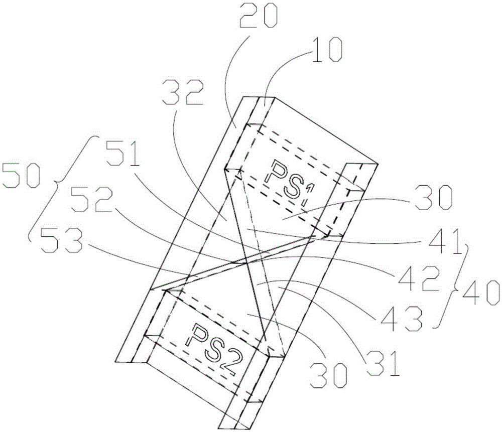
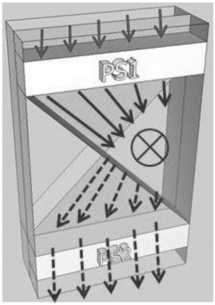
[0036] Please also refer to figure 1 and figure 2 , which is a perspective view of the heat dissipation structure 100 in the first embodiment provided by the present invention. In this embodiment, the heat dissipation structure 100 includes a first air duct 10, a second air duct 20, a partition plate 30, a first partition 40, a second partition 50, a first power unit PS1 and a second power unit PS2.

[0037] The partition plate 30 is disposed between the first air passage 10 and the second air passage 20 . The first parti...


PUM


Abstract

The invention discloses a heat dissipation structure. The heat dissipation structure comprises a first air flue, a second air flue, a separation board arranged between the first air flue and the second air flue, a first partition board, a second partition board, a first power unit and a second power unit. The first partition board is arranged inside the first air flue to divide the first air flue into a first auxiliary air flue and a second auxiliary air flue. The second partition board is arranged inside the second air flue to divide the second air flue into a third auxiliary air flue and a fourth auxiliary air flue. The projection, on the separation board, of the first partition board and the projection, on the separation board, of the second partition board are arranged in a cross mode. The first auxiliary air flue is communicated with the fourth auxiliary air flue and the second auxiliary air flue is communicated with the third auxiliary air flue. The first power unit and the second power unit are arranged inside the first auxiliary air flue and the second auxiliary air flue respectively. The invention further provides an electronic device. According to the heat dissipation structure and the electronic device, through the arrangement of the stereo cross air flues, the heat cascade phenomenon between the first power unit and the second power unit is eliminated, and even current flow of the first power unit and the second power unit is guaranteed.

Description

technical field [0001] The invention relates to the field of heat dissipation, in particular to a heat dissipation structure and an electronic device. Background technique [0002] In the prior art, a photovoltaic inverter includes two power units (PowerStack, PS), and each PS includes a plurality of insulated gate bipolar transistors (Insulated Gate Bipolar Transistor, IGBT). The heat dissipation air ducts of the two PSs are usually connected in series to dissipate heat from the PSs. [0003] In the series cooling air duct, two PSs are placed in series from top to bottom. When the photovoltaic inverter is working, the heat generated by the two PSs forms a thermal cascade. In other words, the heat generated by the upper layer of PS will be transferred to the lower layer of PS, making the temperature of the lower layer of PS higher than that of the upper layer of PS, resulting in a higher overall temperature of the lower layer of PS and shortened life. At the same time, th...

Claims


Application Information

Patent Timeline
Patent Type & Authority Patents(China)
IPC IPC(8): H05K7/20
Inventor 董国卫李泉明杨辉
Owner HUAWEI DIGITAL POWER TECH CO LTD
Why Eureka
Try Eureka