Micro-tension control system and method

A technology of micro-tension control and tension, applied in tension/pressure control, roll speed control, metal rolling, etc., can solve problems such as instability of micro-tension control, frame oscillation, and large fluctuations in tension at the head and tail of the rail

Active Publication Date: 2014-02-12
BERIS ENG & RES CORP
View PDF4 Cites 29 Cited by
  • Summary
  • Abstract
  • Description
  • Claims
  • Application Information

AI Technical Summary

Problems solved by technology

[0004] 1) Due to the large fluctuations in the tension of the head and tail of the rail, the size deviation of the head and tail of the rail is too large, resulting in a longer head and tail. For example, the head and tail size of a high-speed rail produced by a production plant is 3 to 7 meters out of tolerance;
[0005] 2) The micro-tension control link is unstable, and frame oscillation is prone to occur, especially the oscillation of the universal rolling E frame
[0007] 1) Due to the large and unstable tension between the racks, the dynamic AGC of the TCS process control system is unstable, and it is difficult to eliminate the rail size changes caused by the temperature and thickness deviations of the rails. This makes some production plants roll high-speed rails When putting into static AGC function
[0008] 2) The stability of the tension will affect the accuracy of the overall length of the rail
[0009] 3) When the steel biting speed is increased to the rolling speed, the tension will also fluctuate, resulting in fluctuations in the size of the rail
With the rapid development of my country's high-speed railways, the quality requirements for high-speed rails are constantly increasing. However, the existing tandem universal rolling mill MTC micro-tension control technology in my country has an impact on the size of high-speed rails, and there are deficiencies

Method used


Image

  • Micro-tension control system and method
  • Micro-tension control system and method
  • Micro-tension control system and method

Examples


Embodiment Construction

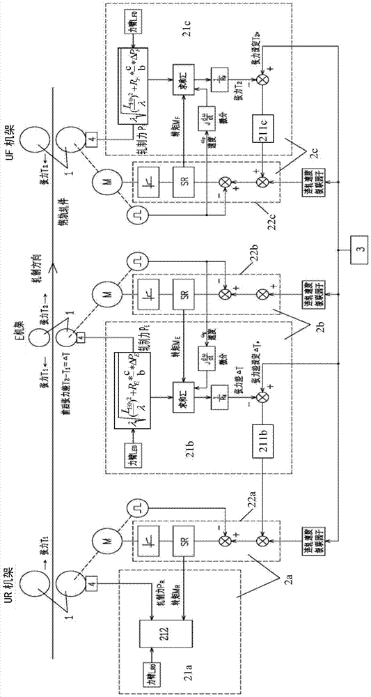
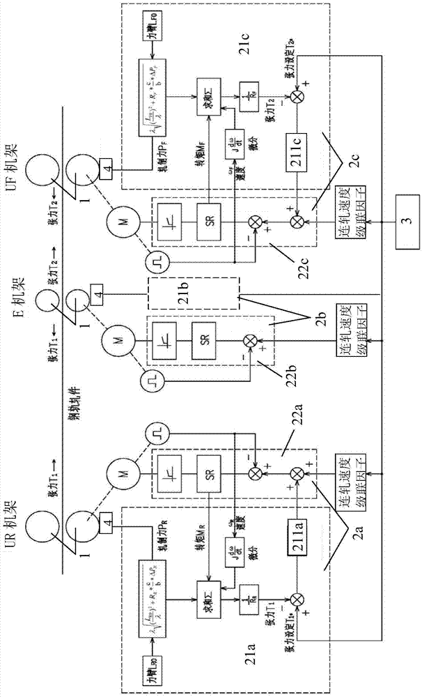
[0080] The micro-tension control system and method of the present invention are mainly aimed at the tandem universal rolling of section steel production, especially the rolling of high-speed steel rails. The tandem universal rolling mill is generally composed of a plurality of racks arranged in the order in which the rolled pieces enter. is the downstream rack of the rack that passes first. Such as Figure 1a and 1b As shown, these stands are divided into U stands and E stands. Since the tandem universal rolling mill is a reversible continuous rolling production line, the U stand upstream of the E stand becomes Becomes the downstream U rack of the E rack. Among them, the U frame includes a pair of horizontal rolls 1 and a pair of vertical rolls, the horizontal roll 1 is driven by the main motor, the vertical roll is a driven roll, and the E frame refers to the edge rolling frame, which only has a pair of horizontal rolls 1 and no vertical rolls roll. The main function of t...


PUM


Abstract

The invention discloses a micro-tension control system and method. In the hot continuous rolling process, when a rolled piece enters a current machine frame and is stably bitten, the current machine frame is kept under speed control, speed control of main motors of machine frames on the upstream of the current machine frame is switched to constant torque control, on the basis, the torque and the rolling force of a main motor of the current machine frame are sampled to calculate the initial length of a rolling force arm, and the tension measurement calculating accuracy is improved. Each machine frame is provided with a pressure measuring head device to directly detect the rolling force, and consideration is given to the situation that the length of the rolling force arm is changed along with changes of the rolling force. Tension between the machine frames is obtained in real time through tension calculating models to form micro-tension closed-loop control to adjust the speeds of the machine frames so as to correct the tension deviations between the machine frames. As for a serial type universal rolling mill, the speed of the E machine frame serves as a standard, the rolling speed of the E machine frame is kept unchanged while speed set values of the other machine frames are adjusted, and real-time control is carried out on dynamic instantaneous values of the tension difference of the E machine frame before and after the adjustment process to guarantee micro-tension rolling of series universal rolling.

Description

technical field [0001] The invention relates to a system and method for controlling the dimensional accuracy of rolled pieces in the hot rolling process of section steel, in particular to a micro tension control system and method in the tandem universal rolling process of high-speed steel rail production. Background technique [0002] When metal products are continuously rolled between the stands of the rolling mill and the preset speed is not ideal, tensile stress occurs in the rolling stock engaged in multiple continuously running stands. If the downstream stand pulls the upstream stand, the rolled piece between the stands will be stretched, and if the upstream stand pushes the downstream stand through the rolled piece, the rolled piece between the stands will be compressed. Stress is caused when the speed of the upstream stand of the rolled stock does not match the difference between the speeds of the next adjacent stand. When the outlet velocity of the upstream rack is ...

Claims


Application Information

Patent Timeline
Patent Type & Authority Applications(China)
IPC IPC(8): B21B37/48B21B37/46B21B38/06B21B38/08
Inventor 刘辉
Owner BERIS ENG & RES CORP
Why Eureka
Try Eureka