Quenching rolling micro-tension control system and method for steel rail

A micro-tension control and rolling force technology, applied in the direction of tension/pressure control, metal rolling, temperature control, etc., can solve the problems of undetectable tension, damage to the size and contour of metal products, and changes in the thickness of rolled pieces, so as to avoid The effect of reheating the rail, reducing the geometric dimension out-of-tolerance, and meeting the quenching requirements

Active Publication Date: 2015-04-29
BERIS ENG & RES CORP
View PDF4 Cites 3 Cited by
  • Summary
  • Abstract
  • Description
  • Claims
  • Application Information

AI Technical Summary

Problems solved by technology

This change will change the thickness of the rolled piece and affect the rolling of the stand
Rolling exhibits a self-stabilizing phenomenon which, however, compromises the size and profile of the metal product
[0003] At present, in terms of hot rolling of plates and strips, looperless micro-tension continuous rolling control is adopted. When there is a temperature difference in the rolled piece, the change in the length of the rolling arm is still ignored, so as to memorize the torque of the main drive motor to control the tension. This kind of "neglecting the change in the length of the rolling arm" is under the condition that there is a temperature difference in the rolled piece, ignoring the influence of the temperature difference on the length of the rolling arm. In terms of rail rolling, the "memory method" that only collects the torque or current of the main motor in the MTC tension control between the rolling mill stands does not eliminate the temperature difference, nor does it install a rolling force detection device, so the length of the rolling arm cannot be obtained. The tension between the racks cannot be detected, resulting in large tension fluctuations
[0004] In addition, high-speed rails require high dimensional accuracy, and the existing tandem universal rolling mills are insufficient in actual use. The fundamental reason is that the following aspects affect AGC thickness control and tension control, and also affect the quenching of high-speed rails. :

Method used


Image

  • Quenching rolling micro-tension control system and method for steel rail
  • Quenching rolling micro-tension control system and method for steel rail
  • Quenching rolling micro-tension control system and method for steel rail

Examples


Embodiment Construction

[0043] In the following, the present invention will be specifically described through exemplary embodiments. It should be understood, however, that elements, structures and characteristics of one embodiment may be beneficially incorporated in other embodiments without further recitation.

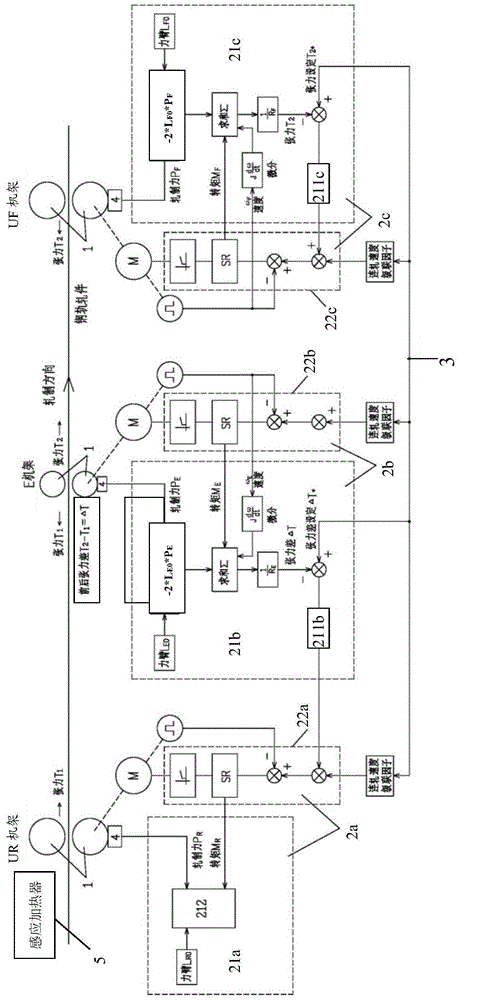
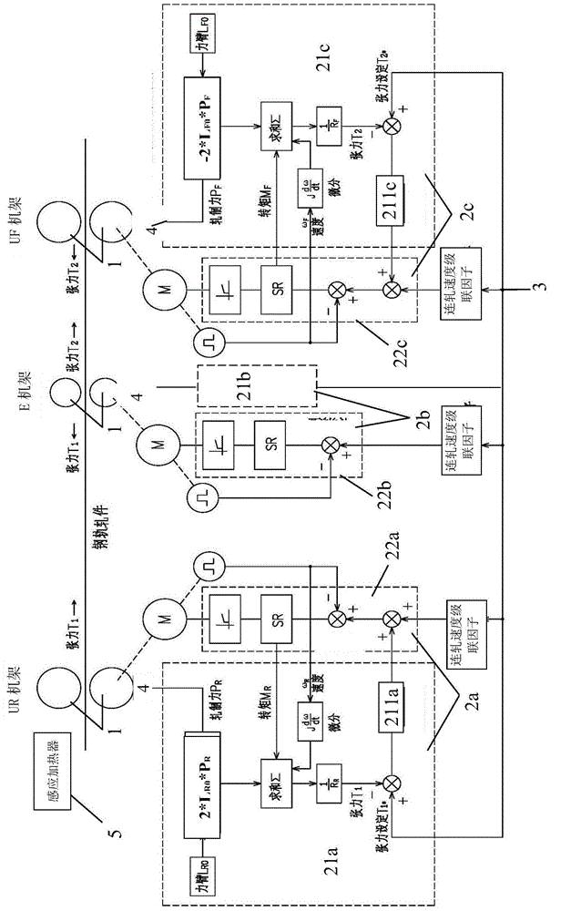
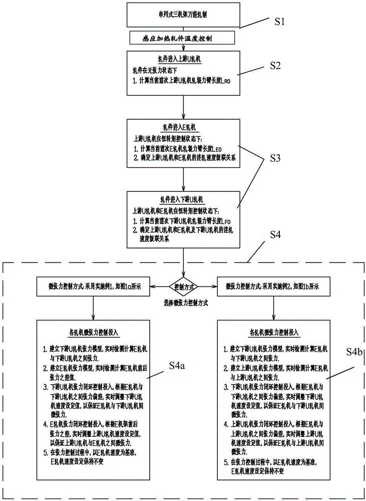
[0044] The micro-tension control system and method of the present invention are mainly aimed at the tandem universal rolling of section steel production, especially the rolling of high-speed steel rails. The tandem universal rolling mill is generally composed of a plurality of racks arranged in the order in which the rolled pieces enter. is the downstream rack of the rack that passes first. Such as Figure 1a and 1b As shown, these stands are divided into U stands and E stands. Since the tandem universal rolling mill is a reversible continuous rolling production line, the U stand upstream of the E stand becomes Becomes the downstream U rack of the E rack. Among them, the U frame includes...


PUM


Abstract

The invention provides quenching rolling micro-tension control system and method for a steel rail. TH system comprises an inductive heating device, a control unit, and a managing unit for controlling and managing the control unit; the control unit under the management of the managing unit converts each rack at the upstream into a constant-torque control state when a rolling part enters one rack and the steel is clamped stably; the control unit comprises a detecting calculating module; the inductive heating device is used for controlling the temperature of the rolling part entering the rack to enable uniform temperature of the rolling part entering the rack, so as to remove the influence of the temperature difference on the length of a actuating arm of a roller; when calculating the actual tension value through the detecting calculating module, the length of the current roller actuating arm is the initial actuating arm length. With the adoption of the system and method, the rolling method under real-time temperature control of the rolling part is performed, and the rolled steel rail is uniform in temperature, so that the quenching requirement can be met; a quenching unit is avoided reheating the steel rail, and as a result, the efficiency is increased.

Description

technical field [0001] The invention relates to a system and method for controlling the dimensional accuracy of rolled pieces during rail rolling, in particular to a micro tension control system and method for providing uniform temperature quenching during rail production tandem universal rolling. Background technique [0002] When metal products are continuously rolled between the stands of the rolling mill and the preset speed is not ideal, tensile stress occurs in the rolling stock engaged in multiple continuously running stands. If the downstream stand pulls the upstream stand, the rolled piece between the stands will be stretched, and if the upstream stand pushes the downstream stand through the rolled piece, the rolled piece between the stands will be compressed. Stress is caused when the speed of the upstream stand of the rolled stock does not match the difference between the speeds of the next adjacent stand. When the outlet velocity of the upstream rack is unbalanc...

Claims


Application Information

Patent Timeline
Patent Type & Authority Applications(China)
IPC IPC(8): B21B37/48B21B38/06B21B37/74
CPCB21B37/48B21B37/74B21B38/06
Inventor 刘辉
Owner BERIS ENG & RES CORP
Why Eureka
Try Eureka