
A micro-tension control system and method for a hydraulic tension warm rolling mill

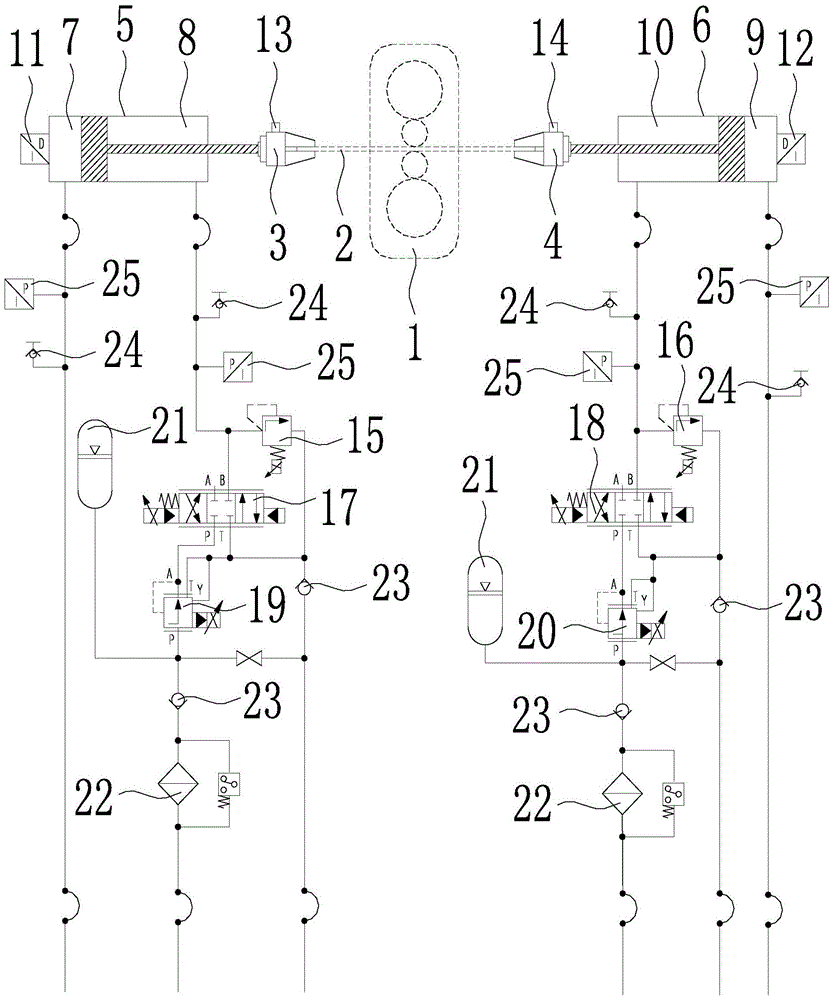
A technology of micro-tension control and hydraulic system, applied in the direction of tension/pressure control, etc., can solve the problems of large calculation errors of forward slip rate and rear slip rate, low precision of tension control, broken strip, etc., and improve the final rolling quality , The tension control method is simple and effective, and the effect of ensuring the precision of tension control

Active Publication Date: 2016-08-31
NORTHEASTERN UNIV LIAONING
View PDF11 Cites 0 Cited by
  • Summary
  • Abstract
  • Description
  • Claims
  • Application Information

AI Technical Summary

Problems solved by technology

However, the existing tension control method is to realize the position closed-loop control and tension closed-loop control of the tension hydraulic cylinder while controlling the flow rate of the servo valve. It is suitable for the cold rolling process, but for the warm rolling process, because the forward slip rate and the rear slip rate are related to factors such as friction coefficient, reduction rate, thickness calculation accuracy, etc., and the friction coefficient is related to the temperature of the rolled piece, the temperature of the roll and the surface roughness of the roll Therefore, the calculation error of the front slip rate and the back slip rate in the warm rolling process is relatively large, so that the tension control accuracy in the warm rolling process is not high, and the strip breakage often occurs during the rolling process
Therefore, the existing tension control method is not suitable for hydraulic tension warm rolling mill

Method used


Image

  • A micro-tension control system and method for a hydraulic tension warm rolling mill

Examples


Embodiment

[0033] In this embodiment, the rolled piece 2 is an AZ31 magnesium alloy strip, the initial size is 3.95mm×200mm×1000mm, and the target thickness size is 0.7mm; the size of the backup roll of the hydraulic tension warm rolling mill is φ480×350mm, and the size of the work roll is φ200× 370mm; the cylinder diameter of the left and right tension hydraulic cylinders is 90mm, the diameter of the piston rod is 63mm, and the stroke is 2100mm; the flow rate of the left and right proportional pressure reducing valves is 40L / min; the model of the left and right servo valves is D661; The flow rate of the right proportional relief valve is 40L / min; the maximum range of the left and right displacement sensors is 2150mm, and the measurement accuracy is 0.01mm; the maximum range of the left and right tensiometers is 10kN, and the measurement accuracy is 0.1kN; The high pressure oil provided by the high pressure oil source of the system is 21MPa, and the low pressure oil provided by the low pr...


PUM


Abstract

The invention discloses a micro-tension control system and method of a hydraulic tension warm rolling mill, belonging to the technical field of tension control of hydraulic tension rolling mills. The micro-tension control system of the present invention includes two sets of tension hydraulic cylinders and a hydraulic system on the left and right. The hydraulic system includes a proportional overflow valve, a servo valve and a proportional pressure reducing valve. During the tension establishment stage of the rolled piece and the rolling stage of the rolled piece And the parking stage at the end of the rolling pass, by controlling the opening and closing states of the left and right sets of proportional relief valves, servo valves and proportional pressure reducing valves, and setting the corresponding control amount, the tension hydraulic cylinder can Tension closed-loop adjustment is performed through proportional pressure reducing valve and tensiometer, or tension closed-loop adjustment is performed through proportional relief valve and tensiometer. During the loading and unloading stages of the rolled piece, the tension hydraulic cylinder performs position closed-loop adjustment through the servo valve and displacement sensor. . The tension control mode of the present invention is simpler and more effective, effectively ensures the precision of tension control, and realizes micro-tension rolling of relatively brittle or hard-to-deform metal strips.

Description

technical field [0001] The invention belongs to the technical field of tension control of hydraulic tension rolling mills, in particular to a micro tension control system and method of hydraulic tension warm rolling mills. Background technique [0002] At present, the hydraulic tension warm rolling mill used in the experiment can conduct on-line heating and tension rolling of a single piece of metal strip sample, creating technical conditions for carrying out experimental research on the warm rolling process of metals that are difficult to deform at room temperature and for realizing the industrial production of thin metal strips . [0003] For metal strips that are relatively brittle or difficult to deform at room temperature, it is usually necessary to carry out warm rolling under the condition of micro tension (<3kN) after online heating. In order to ensure the rolling accuracy of the rolled piece, it is necessary to ensure the control of micro tension precision. How...

Claims


Application Information

Patent Timeline
Patent Type & Authority Patents(China)
IPC IPC(8): B21B37/48
CPCB21B37/48
Inventor 孙涛王贵桥李建平牛文勇
Owner NORTHEASTERN UNIV LIAONING
Learn More