Multifunctional pipe welding fixture

A pipe body and steel pipe technology, which is applied in the field of pipeline welding multifunctional tooling, can solve the problems of long welding time, poor welding quality, complicated process, etc., and achieve the effect of improving work efficiency and quality, and good welding quality

Inactive Publication Date: 2014-02-12
周国平
View PDF0 Cites 0 Cited by
  • Summary
  • Abstract
  • Description
  • Claims
  • Application Information

AI Technical Summary

Problems solved by technology

[0003] In order to overcome the existing shortcomings of long welding time, complicated proces

Method used


Image

  • Multifunctional pipe welding fixture

Examples


Example Embodiment

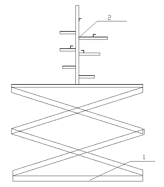
[0009] Such as figure 1 It is a schematic diagram of the structure of the present invention. A multifunctional tooling for pipe welding includes a mobile lifting platform 1 and a welding bracket 2. The welding bracket 2 is installed on the mobile lifting platform 1. When the weldment needs to be welded, the weldment can be fixed on the fixture bracket 2 according to the shape of the weldment on the tooling, so that each welding joint is in a flat fillet position, which is beneficial to ensure the welding quality; the welding bracket 2 can also be Rotate at any position on the mobile lifting platform 1, according to the shape of the pipeline, rotate the corresponding angle, so that the workpiece is always in the position where welding is the easiest to ensure welding quality, improve work efficiency; welding can also be based on the height of the welder , The height of the weldment position, and the height of the mobile lifting platform 1 for welding habits.


PUM


Abstract

The invention relates to the technical field of pipeline delivery equipment, in particular to a high-strength steel pipe comprising a pipe body. Keels which are 'L'-shaped steel angles are arranged on the pipe body and fastened on the outer surface of the pipe body. The keels which are the 'L'-shaped steel angles and have high strength in crumpling resistance and distortion resistance are arranged on the pipe body and fastened on the outer surface of the pipe body, so that the pipe body can be reinforced and protected, collapse resistance and compression resistance are realized, overall strength of the pipe body is enhanced, and cost is saved.

Description

Technical field [0001] The invention relates to a pipeline welding technology, in particular to a pipeline welding multifunctional tooling. Background technique [0002] The Harmony 5 locomotive air brake pipeline has complex shapes and high welding requirements, and each pipeline has a different wall thickness and shape. When welding, because the pipeline is complicated and each joint is in a different position, each joint is welded. It takes a lot of man-hours, and the quality cannot be guaranteed. It takes one working day to complete the whole set of pipeline welding, which does not include inspection, grinding, pressure test, etc., which cannot meet the production node. Summary of the invention [0003] In order to overcome the existing disadvantages of long welding time, complicated process, and poor welding quality, the present invention provides a multifunctional tooling for pipe welding. [0004] The technical solution adopted by the present invention to solve its technical...

Claims


Application Information

Patent Timeline
IPC IPC(8): B23K37/047
CPCB23K37/047B23K37/0426B23K2101/06
Inventor 周国平
Owner 周国平
Why Eureka
Try Eureka