Blow molding device for plastic boxes

A blow molding device and box body technology, applied in the field of plastic fuel tank manufacturing equipment, can solve the problems of clip plate damage, increased parts consumption, long production stop time, etc., and achieve the effect of shortening distance and reducing height

Active Publication Date: 2014-02-12
YAPP AUTOMOTIVE PARTS
View PDF3 Cites 1 Cited by
  • Summary
  • Abstract
  • Description
  • Claims
  • Application Information

AI Technical Summary

Problems solved by technology

The flash at the lower part of the box consists of three parts. F3 section is the height between the lower parting line of the mold and the lower edge of the mold frame, usually 70-80mm, corresponding to F2; F4 is the distance between the lower frame of the mold and the clamping plate , because the clamping plate in the traditional structure is located under the mold base and driven independently, the distance from the mold frame is usually 20mm, and no gap can be achieved, because the blank will squeeze the clamping plate at the moment of mold closing, which is easy to cause clamping The damage of the material plate; even in the gap of 20mm, the damage of the clamping plate is still relatively frequent, which increases the consumption of accessories, and it takes about 20-30 minutes to replace the clamping plate each time, causing the production to stop for a long time and affecting the production efficiency; F5 is the height of the protruding section at the lower end of the clamping plate, which is determined by the process

Method used


Image

  • Blow molding device for plastic boxes
  • Blow molding device for plastic boxes
  • Blow molding device for plastic boxes

Examples


Embodiment Construction

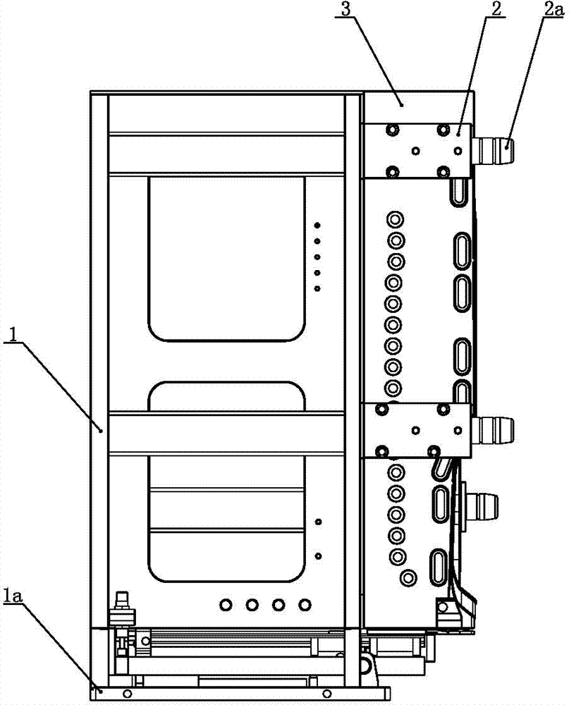
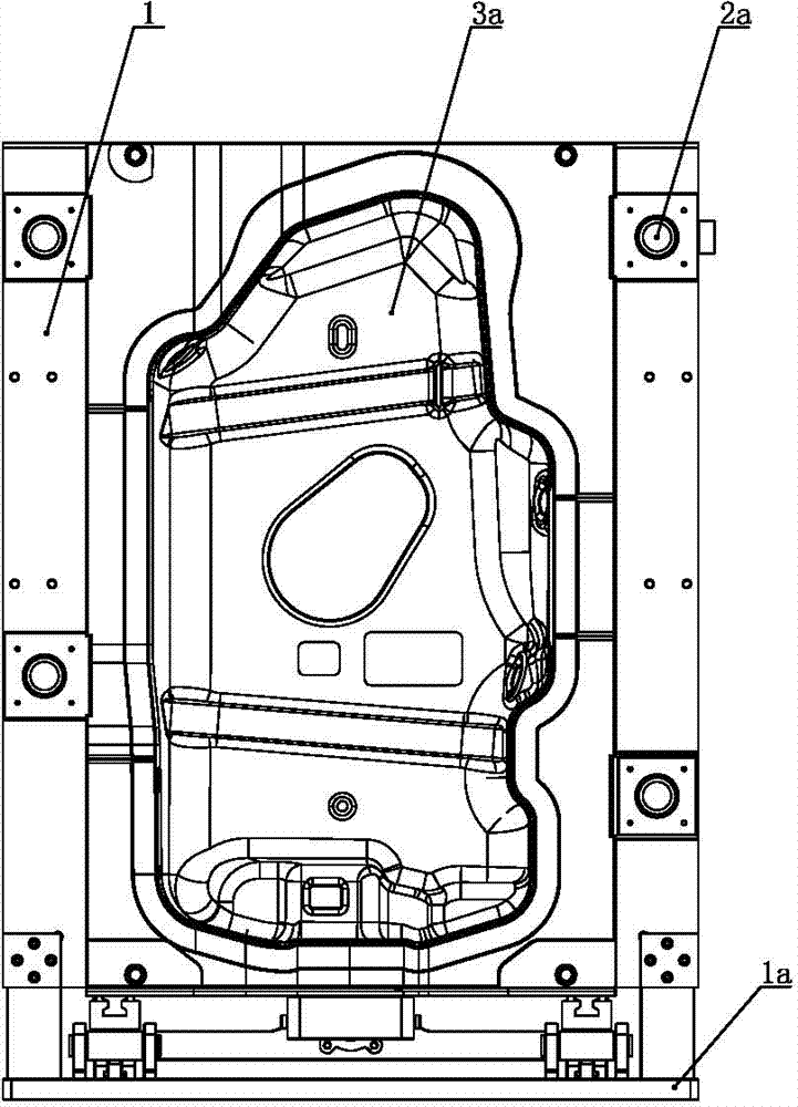
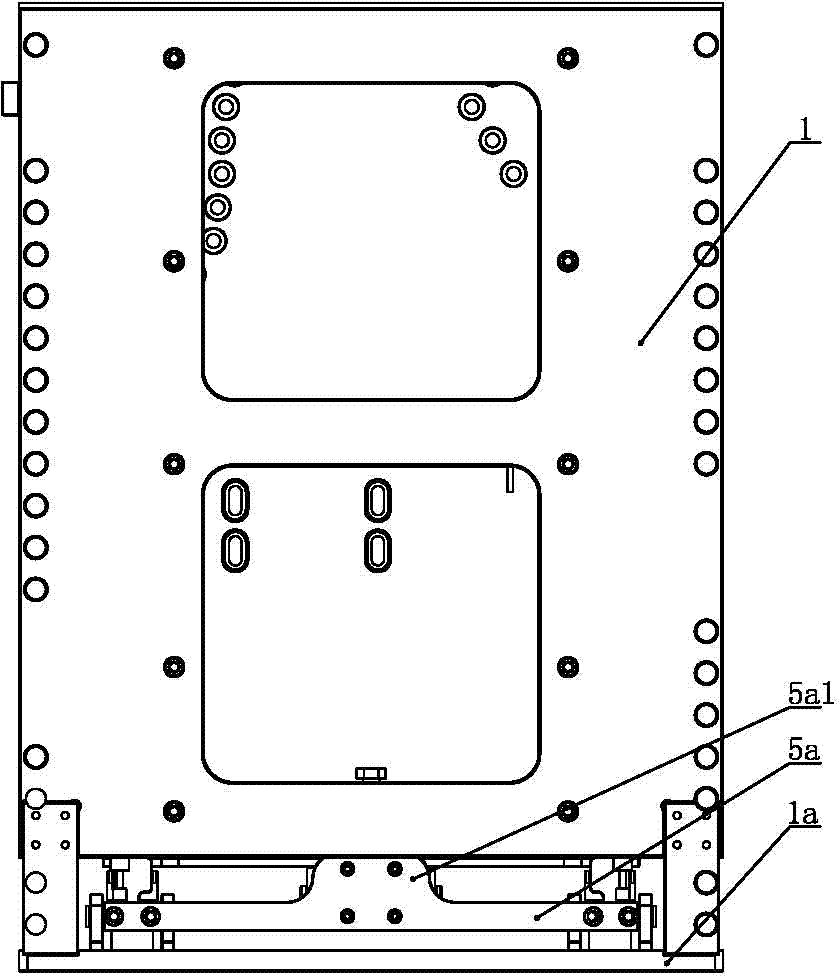
[0036] Such as Figure 1 to Figure 6 As shown, the blow molding device of the plastic box of the present invention comprises left and right mold bases which are respectively located at the left and right sides of the parison and which can move towards each other. The left and right half molds are respectively installed on the opposite end faces of the frame, and the opposite end faces of the left and right half molds are respectively provided with a cavity 3a having the same shape and size as the left and right halves of the fuel tank. There is a clamping device. Because the left and right mold bases are symmetrical, for the sake of simplicity, only the left mold base 1 and half mold 3 are shown in the figure. The mold base 1 is respectively provided with a mold positioning block 2 and a mold positioning pin 2a. When the mold positioning pin 2a is inserted into the pin hole of the mold positioning block 2, the left and right half molds are aligned and enter the mold closing. ...


PUM


Abstract

The invention relates to a blow molding device for plastic boxes. The blow molding device comprises a left mold base and a right mold base which can move oppositely, wherein the bottoms of the left mold base and the right mold base are provided with mold base bottom plates respectively, a left half mold and a right half mold are arranged on the opposite end surfaces of the left mold base and the right mold base respectively, a left cavity and a right cavity which are the same as a left fuel tank and a right fuel tank in shape and size are formed on the opposite end surfaces of the left half mold and the right half mold respectively, material clamping devices are arranged on the left mold base and the right mold base respectively, the material clamping devices comprise material clamping plates respectively, the material clamping plates can stretch out oppositely to clamp a parison, the upper surface of the material clamping plate is closely attached to the bottom wall of the corresponding half mold and is driven by a material clamping plate driving cylinder, the material clamping plate driving cylinders are fixed on material clamping device bases respectively, the material clamping device bases are arranged on the mold base bottom plates respectively; when the material clamping plate stretches out, the material clamping device base is locked, and the material clamping device base can rotate during mold assembly, so that the material clamping plate can be prevented from damage. The blow molding device for the plastic boxes can reduce the flash height after the box is formed and improve the utilization rate of the parison.

Description

technical field [0001] The invention relates to a plastic fuel tank manufacturing equipment, in particular to a blow molding device for a plastic tank body. Background technique [0002] The blow molding device of the existing plastic box includes left and right mold bases which are respectively located on the left and right sides of the parison and can move towards each other. Left and right half molds are respectively installed on the top, and the opposite end faces of the left and right half molds are respectively provided with left and right mold cavities with the same shape and size as the left and right halves of the fuel tank. [0003] During blow molding, a parison is continuously extruded downward through the co-extrusion die. When the length reaches the set value, the stretching rod slides forward and backward to stretch the lower end of the parison. After the stretching material is in place, the clamping plate extends from the left and right sides to clamp and cl...

Claims


Application Information

Patent Timeline
Patent Type & Authority Applications(China)
IPC IPC(8): B29C49/48B29C49/72
Inventor 孙岩姜林徐松俊葛学继高德俊
Owner YAPP AUTOMOTIVE PARTS
Why Eureka
Try Eureka