
Pneumatic tire

A technology for pneumatic tires and tires, which is applied to tire parts, tire treads/tread patterns, transportation and packaging, and can solve problems such as poor noise performance, increased pumping sound, and reduced ground contact area of ​​the tread

Active Publication Date: 2014-02-12
SUMITOMO RUBBER IND LTD
View PDF6 Cites 8 Cited by
  • Summary
  • Abstract
  • Description
  • Claims
  • Application Information

AI Technical Summary

Problems solved by technology

However, in this method, since the ground contact area of ​​the tread portion is reduced, there is a problem that performance on icy roads deteriorates.
In addition, when the volume of the lateral groove is large, there is a problem that the air in the lateral groove flows out along with the rolling of the tire, and the pumping sound etc. generated thereby increases, so that the noise performance is also deteriorated.
Thus, there is a reciprocal relationship between snow performance, ice performance, and noise performance, making it difficult to improve all of the above performances in a balanced manner

Method used


Image

  • Pneumatic tire
  • Pneumatic tire
  • Pneumatic tire

Examples


Embodiment

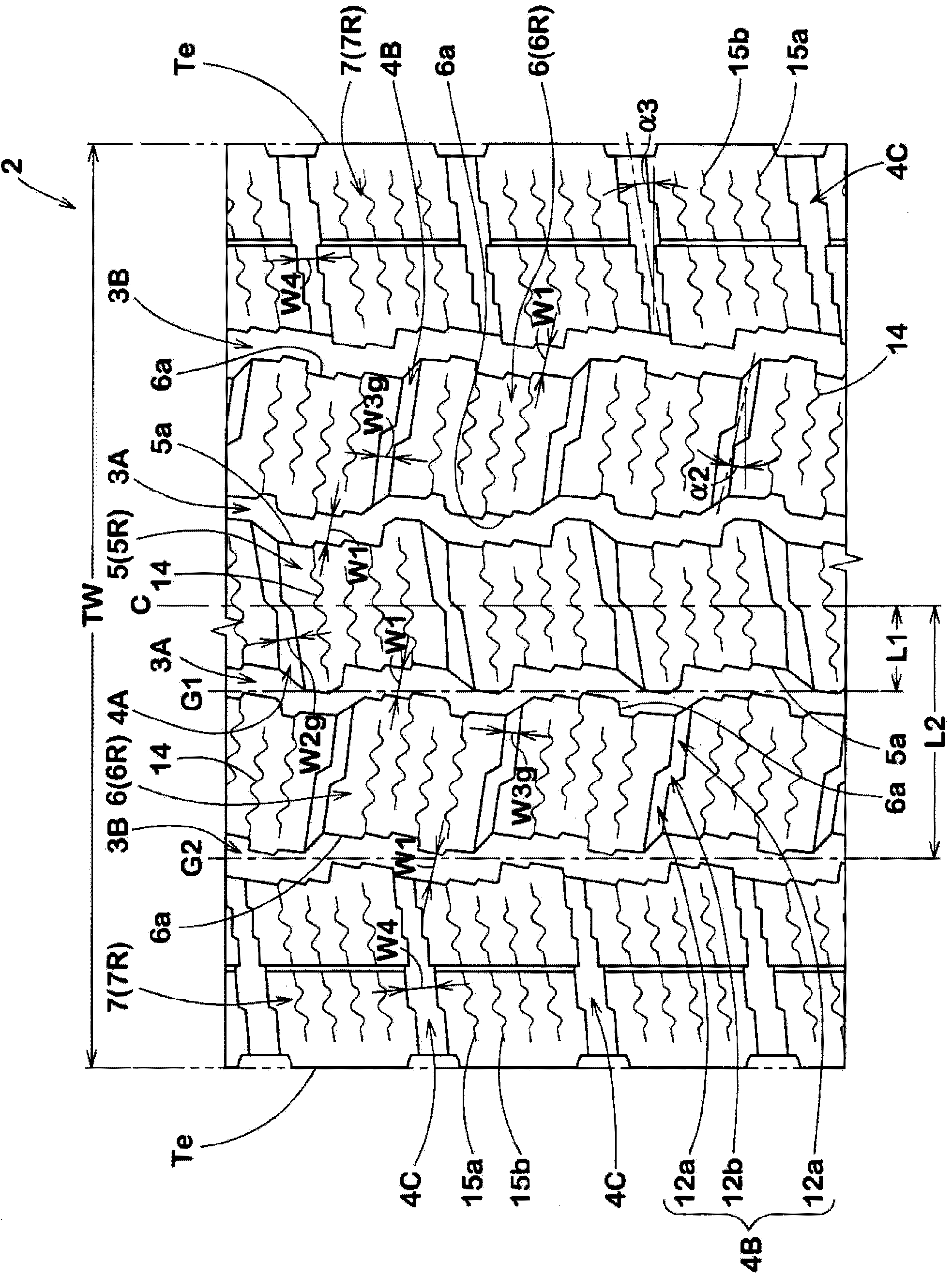
[0060] Based on the specifications in Table 1, prototypes with figure 1 Pneumatic tires with the basic pattern and the size of 195 / 80R15 were tested, and the noise performance, icy road performance (braking force) and snow road performance of each tire were tested. Among them, the common specifications are as follows.

[0061] Tread contact width TW: 160mm

[0062]

[0063] Groove width W1: 3mm~5mm

[0064] Groove depth: 12.3mm

[0065] The ratio of the tire axial distance L1 of the groove center line of the central main groove to the tread contact width TW (L1 / TW): 0.09

[0066] The ratio of the tire axial distance L2 of the groove center line of the shoulder main groove to the tread contact width TW (L2 / TW): 0.28

[0067]

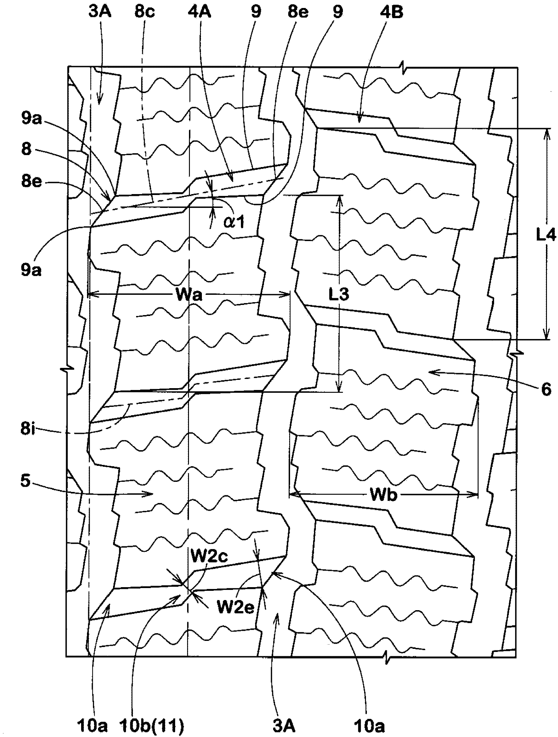
[0068] Angle α1 of the central transverse groove: 9°

[0069] Angle α2 of the middle transverse groove: 12°

[0070] Groove width W4 of shoulder transverse groove: 3mm~5mm

[0071] Angle α3 of shoulder transverse groove: 10°

[0072] Groove de...


PUM


Abstract

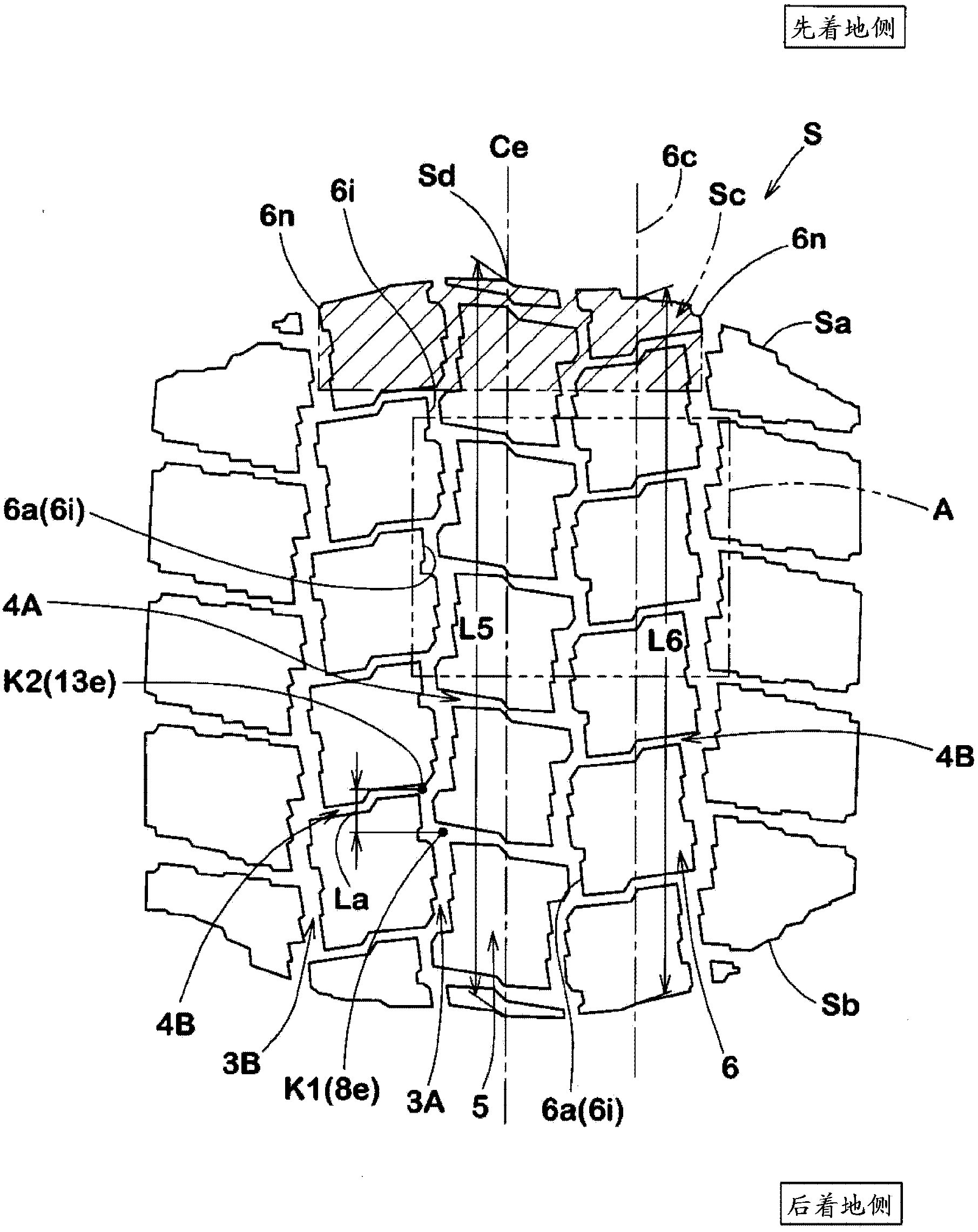
The invention provides a pneumatic tire which can uniformly improve the noise performance, snow rode performance, and ice rode performance. The pneumatic tire is provided with a center pattern block (5) and a middle pattern block (6). The two pattern blocks are provided with a plurality of sipes (14). A central transverse groove (4A) is inclined at an angle in the range of 5-20 degrees, and the average groove width is 7-15% of the maximum length (L3) of the center pattern block. A middle transverse groove (4B) is inclined at an angle in the range of 5-25 degrees, and the average groove width is 7-11% of the maximum length (L4) of the middle pattern block (6). In the grounding surface under the standard load state, the tire circumferential distance (La) of a first intersection point (K1) and a second intersection point (K2) is 0.75-1.00 times of the difference (L5-L6) of the length of the grounding surface at the tire equator position (Ce) and the length of the grounding surface at the middle position (6c) of the middle pattern block, and the first intersection point is obtained by the intersection of the central transverse groove and a central main groove (3A), and the second intersection point is obtained by the intersection of the middle transverse groove and the central main groove.

Description

technical field [0001] The present invention relates to a pneumatic tire which improves noise performance, snow road performance and icy road performance in a balanced manner. Background technique [0002] Pneumatic tires for winter use not only on snowy and icy roads but also on asphalt roads, etc. Therefore, it is required to improve not only snow performance and icy performance but also noise performance in such winter pneumatic tires. [0003] For example, in order to improve performance on snowy roads, it has been proposed to increase the volume of lateral grooves in the tread portion for the purpose of increasing snow column shear force. However, in this method, since the ground contact area of ​​the tread portion is reduced, there is a problem that performance on icy roads is deteriorated. In addition, when the volume of the lateral groove is large, there is a problem that the air in the lateral groove flows out along with the rolling of the tire, thereby increasing...

Claims


Application Information

Patent Timeline
Patent Type & Authority Applications(China)
IPC IPC(8): B60C11/03B60C11/117
CPCB60C11/03B60C11/11B60C2011/0341B60C2011/0365
Inventor 木村龙雄松田阳介
Owner SUMITOMO RUBBER IND LTD
Learn More