Diesel hydraulic lifting machine

A hoist, hydraulic technology, applied in cranes, transportation and packaging, load hoisting components, etc., can solve the problems of low maintenance cost and poor adaptability, and achieve the effect of low maintenance cost, simple structure and smooth operation

Inactive Publication Date: 2014-02-12
姚芸
View PDF5 Cites 5 Cited by
  • Summary
  • Abstract
  • Description
  • Claims
  • Application Information

AI Technical Summary

Problems solved by technology

[0009] The purpose of the present invention is to provide an improvement scheme of hoisting machine, which can overcome the defects ...

Method used


Image

  • Diesel hydraulic lifting machine
  • Diesel hydraulic lifting machine

Examples


Embodiment Construction

[0037] Hereinafter, embodiments of the present invention will be described in detail with reference to the accompanying drawings. Examples of the embodiments are shown in the accompanying drawings, wherein the same or similar reference numerals indicate the same or similar components or components with the same or similar functions. The embodiments described below with reference to the accompanying drawings are exemplary, and are only used to explain the patent, and cannot be construed as a limitation to the patent.

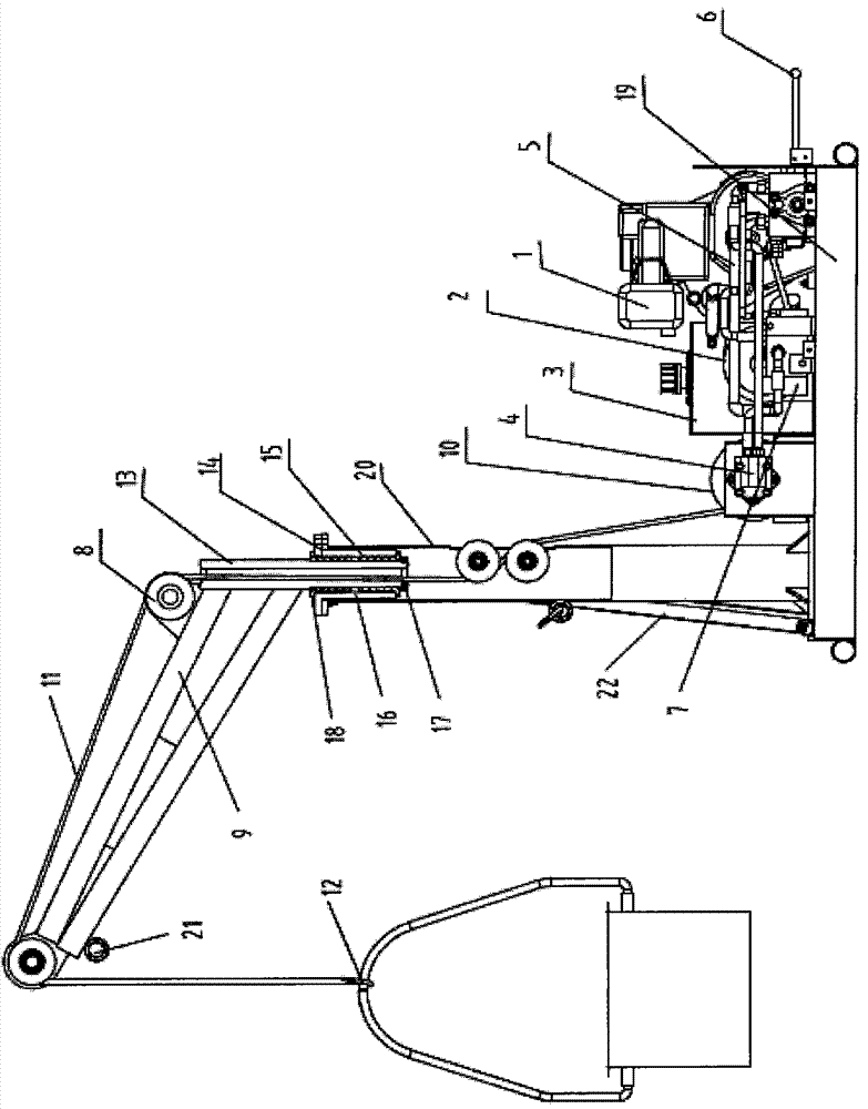
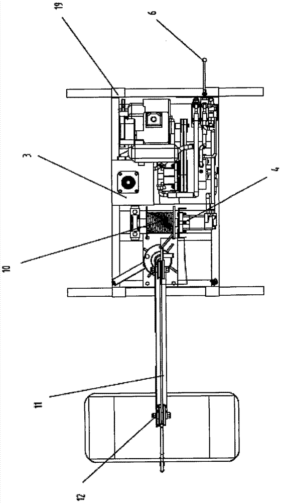
[0038] The diesel engine provides power to drive the hydraulic pump to suck oil from the hydraulic oil tank and input the balance valve to the hydraulic motor after being adjusted by the controller to give a controllable and stable power to the hydraulic motor.

[0039] The rotation of the hydraulic motor drives the steel wire drum to pull the steel wire through the guide wheels to lift the heavy object, and when the height is required, the brake is controlled by the c...


PUM


Abstract

The invention relates to a diesel hydraulic lifting machine. The diesel hydraulic lifting machine comprises a support frame device part, a power device part, a hydraulic device part, a lifting and pulling device part and a rotary device part. According to the invention, power is provided through a diesel engine, and control power is provided through a hydraulic motor, and the stable running is achieved when loaded objects fall off by utilizing a balanced valve operating principle.

Description

Technical field [0001] The invention belongs to the field of mechanical hoisting, and particularly refers to a diesel hydraulic hoist. Background technique [0002] For lifting materials under 300 kg, or for residents of high-rise buildings, who can easily lift heavy daily necessities from downstairs and lift and unload small goods in various occasions, hoisting machines are the best choice. Because of its simple structure, easy installation, compactness, and single-phase power source, the hoist has a wide range of uses. This kind of small crane is also called electric hoist, and it is also widely used in modern industrial production lines, assembly lines, assembly machines, logistics transportation and other occasions such as machinery manufacturing, electronics, automobiles, shipbuilding, workpiece assembly, and high-tech industrial zones. For work in warehouses, docks, ingredients, hanging baskets and working places with narrow space, it can show its excellent quality. It is...

Claims


Application Information

Patent Timeline
IPC IPC(8): B66C23/16B66C23/62B66C13/20
Inventor 姚芸
Owner 姚芸
Why Eureka
Try Eureka