
Pressure-controllable hydraulic press for liquid crystal display machining

A liquid crystal screen and press technology, applied to presses, stamping machines, manufacturing tools, etc., can solve the problems of high cost of high-pressure oil pumps, large power consumption, increased production costs, etc., and achieve the effect of shortening the molding time

Pending Publication Date: 2021-06-11
常州红光仪表配件有限公司
View PDF0 Cites 0 Cited by
  • Summary
  • Abstract
  • Description
  • Claims
  • Application Information

AI Technical Summary

Problems solved by technology

Its shortcoming is that the press must be equipped with two sets of medium pressure and high pressure oil pumps, and the high pressure oil pump is expensive and consumes a lot of power.
[0003] In the process of processing liquid crystal screens in the existing hydraulic presses, it is often necessary to equip different hydraulic presses according to different liquid crystal screens because the pressure of the hydraulic presses is fixed, which greatly increases the production cost, and reduced productivity

Method used


Image

  • Pressure-controllable hydraulic press for liquid crystal display machining
  • Pressure-controllable hydraulic press for liquid crystal display machining
  • Pressure-controllable hydraulic press for liquid crystal display machining

Examples


Embodiment Construction

[0018] The following will clearly and completely describe the technical solutions in the embodiments of the present invention with reference to the accompanying drawings in the embodiments of the present invention. Obviously, the described embodiments are only some, not all, embodiments of the present invention. Based on the embodiments of the present invention, all other embodiments obtained by persons of ordinary skill in the art without making creative efforts belong to the protection scope of the present invention.

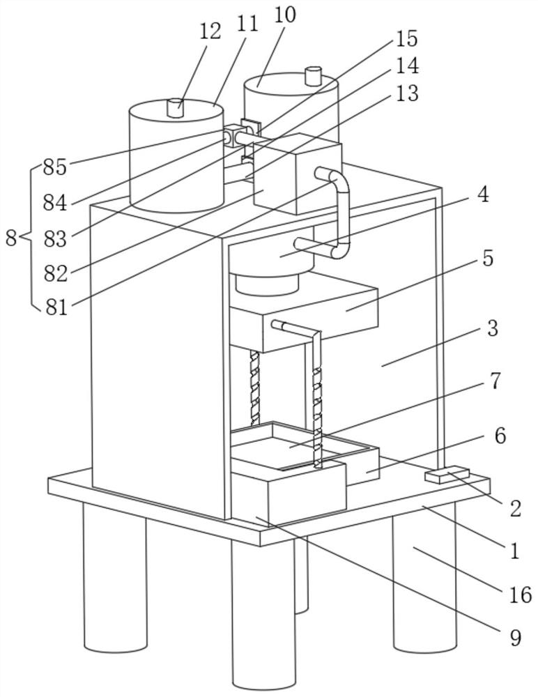
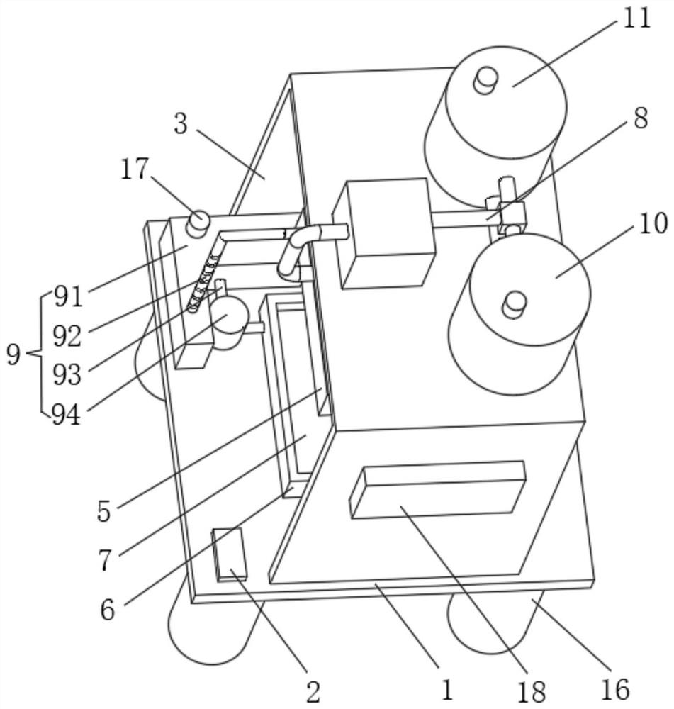
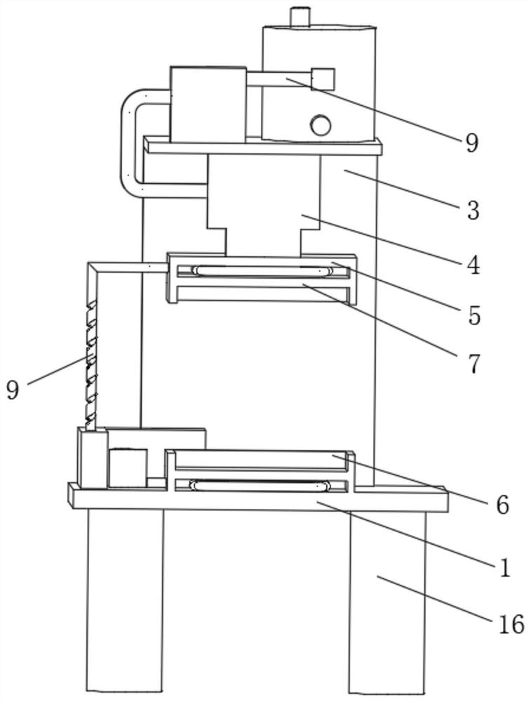
[0019] see Figure 1-3 , the present invention provides a technical solution: a pressure-controllable hydraulic press for liquid crystal screen processing, including a base plate 1 and a hydraulic unit 8;

[0020] Bottom plate 1: The upper surface of the bottom plate 1 is provided with a side plate 3, which is an "L"-shaped plate. The oil tanks 10 are connected through the shared oil pipe 13, and the connection between the shared oil pipe 13 and the second oi...


PUM


Abstract

The invention discloses a pressure-controllable hydraulic press for liquid crystal display machining. The pressure-controllable hydraulic press comprises a bottom plate and a hydraulic unit, wherein a side plate is arranged on the upper surface of the bottom plate, the side plate is an L-shaped plate, a first oil tank and a second oil tank are sequentially arranged on the upper surface of the side plate, the first oil tank communicates with the second oil tank through a shared oil pipe, a bottom electromagnetic valve is arranged at the communicating position of the shared oil pipe and the second oil tank, the upper surface of an inner cavity of the side plate is fixedly connected with the fixed end of a hydraulic push rod, and the telescopic end of the hydraulic push rod is fixedly connected with an upper die groove. According to the pressure-controllable hydraulic press for liquid crystal display processing, the hydraulic unit provides power for the hydraulic push rod, the power of the hydraulic unit can be increased or decreased through the first oil tank, the second oil tank, the shared oil pipe, the bottom electromagnetic valve and a top electromagnetic valve, and liquid crystal screen assemblies can be cooled after being machined through a cooling unit.

Description

technical field [0001] The invention relates to the technical field of liquid crystal screen processing, in particular to a pressure-controllable hydraulic press for liquid crystal screen processing. Background technique [0002] In the prior art, a hydraulic press has a frame, an oil pump, an electric motor, an overflow valve, an electromagnetic reversing valve and an oil cylinder. In order to increase the pressure at the piston end of the oil cylinder, the press is often equipped with two oil pumps, a medium-pressure oil pump and a high-pressure oil pump, and the high-pressure oil pump is used to supply oil during the working stroke of the press, that is, when the workpiece is pressed. Its shortcoming is that the press must be equipped with two sets of oil pumps of medium pressure and high pressure, and the cost of the high pressure oil pump is high and consumes a lot of power. [0003] In the process of processing liquid crystal screens in the existing hydraulic presses,...

Claims


Application Information

Patent Timeline
IPC IPC(8): B30B1/32B30B15/16B30B15/02B30B15/34
CPCB30B1/32B30B15/02B30B15/161B30B15/34
Inventor 周建民
Owner 常州红光仪表配件有限公司
Learn More