Cam-type sealing machine for cylindrical batteries

A cylindrical battery and sealing machine technology, which is used in the manufacture of primary batteries, secondary batteries, circuits, etc., can solve the problems of excessively fast bending deformation of the sealing, easy burrs at the sealing, and increased gas consumption, and achieves easy operation and production efficiency. high effect

Active Publication Date: 2013-02-06
ZHUHAI HIGRAND ELECTRONICS TECH
View PDF3 Cites 10 Cited by
  • Summary
  • Abstract
  • Description
  • Claims
  • Application Information

AI Technical Summary

Problems solved by technology

[0003] The air-liquid pressurized cylinder sealing machine adopts the air-liquid pressurized cylinder and pneumatic mechanism to seal the movable positioning column battery on the base. The degree of automation is not high, and the air consumption of the air-liquid pressurized cylinder is large. If the speed increases The gas consumption has increased significantly, which requires high infrastructure; at the same time, it is not easy to control the size of the air pressure and the stroke of the booster with the gas-hydraulic booster cylinder, and it is not easy to control the pressure and speed of the punch when sealing.
[0004] Punch-type sealing machine adopts two-petal locking tile, the positioning is not accurate, the sealing is bent and deformed too quickly, it is easy to punch the battery, the sealing is easy to produce burrs, the sealing quality is unstable, and it cannot provide a high-level shaping device. It is difficult to demold the battery, and the efficiency is relatively low Low

Method used


Image

  • Cam-type sealing machine for cylindrical batteries
  • Cam-type sealing machine for cylindrical batteries
  • Cam-type sealing machine for cylindrical batteries

Examples


Embodiment Construction

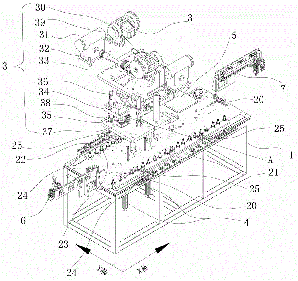
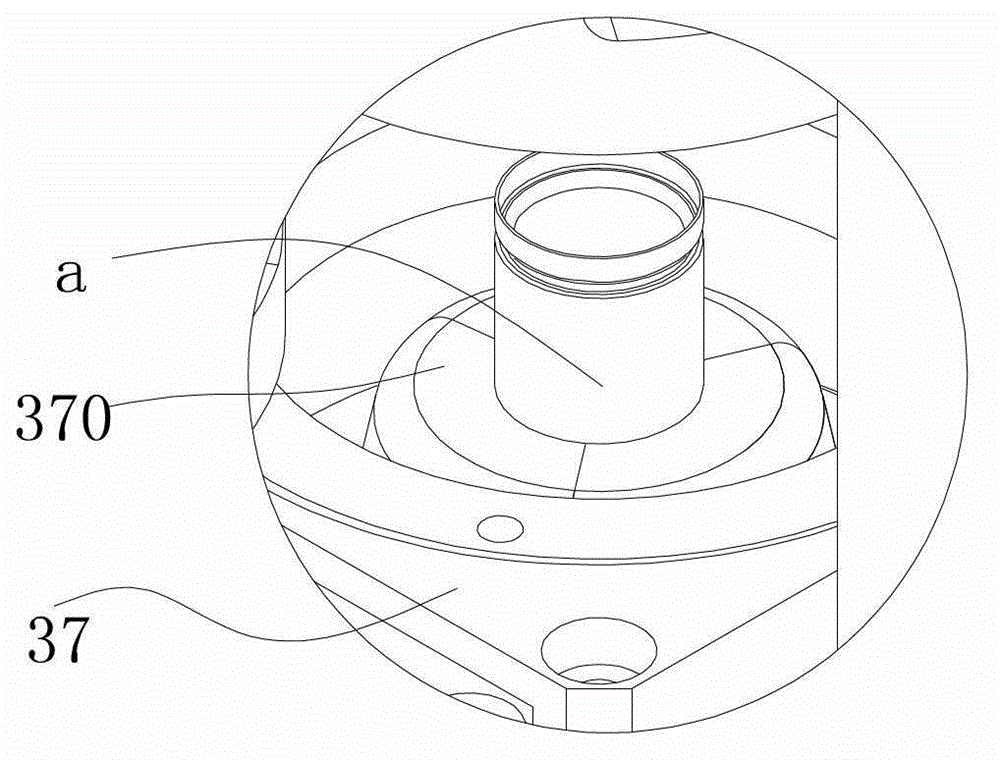
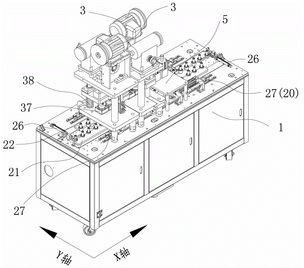
[0025] A cam type cylindrical battery sealing machine, such as Figure 1 to Figure 6 As shown, it includes a machine base 1, a rail transfer device 2 and two sets of sealing die devices 3, the linear transfer track of the rail transfer device 2 is arranged on the platform of the machine base 1, and two sets of sealing die devices 3 are sequentially arranged along the transfer rails; The track transfer device 2 includes a transfer drive device 20 and a pair of front and rear transfer grippers (21, 22) symmetrically arranged along both sides of the transfer track, and the butt joints of the pair of front and rear transfer grippers (21, 22) are respectively spaced and misaligned. A plurality of clamping columns 23 for laterally shifting the cylindrical batteries (not shown) are provided, and the platform of the machine base 1 is respectively provided with clamps for forward and backward transfer and laterally reciprocating displacement of the clamping plates (21, 22). Horizontal ...


PUM


Abstract

The invention relates to a cam-type sealing machine for cylindrical batteries. The cam-type sealing machine comprises a baseframe, a track delivery device and at least one set of sealing mold device, wherein linear transfer tracks of the track delivery device are arranged on the platform of the baseframe; the track delivery device comprises a delivery driving device, as well as a front transfer clamping plate and a rear transfer clamping plate which form a pair, a plurality of clamping pillars for clamping and sending the cylindrical batteries to achieve transverse shift are respectively arranged at the joint between the front transfer clamping plate and the rear transfer clamping plate, transverse linear slide rails facilitating transverse reciprocating movement of the front transfer clamping plate and the rear transfer clamping plate are respectively arranged on the platform of the baseframe, and longitudinal linear slide rails are respectively arranged on the front transfer clamping plate and the rear transfer clamping plate; the transfer driving device comprises an X-axis power source and a Y-axis power source; and the sealing mold device comprises a driving motor, a clutch, a reducing mechanism, a cam mechanism, a slide block mechanism, a sealing die, a sliding pole and a lower die, the lower die is mounted on the transfer tracks on the platform of the baseframe, the slide block mechanism and the sealing die are mutually connected and slide along the sliding pole, and the sliding pole is equipped with a return spring.

Description

【Technical field】 [0001] The invention relates to battery manufacturing equipment, in particular to a cam type cylindrical battery sealing machine. 【Background technique】 [0002] In the production of cylindrical batteries, sealing is a very important part. In the prior art, most of the equipment for sealing batteries adopts gas-hydraulic pressurized cylinder sealing machines or punch-type sealing machines. [0003] The air-liquid pressurized cylinder sealing machine adopts the air-liquid pressurized cylinder and pneumatic mechanism to seal the movable positioning column battery on the base. The degree of automation is not high, and the air consumption of the air-liquid pressurized cylinder is large. If the speed increases The air consumption has increased significantly, which requires high infrastructure; at the same time, it is not easy to control the size of the air pressure and the stroke of the pressurization by using the air-hydraulic booster cylinder, and it is not ea...

Claims


Application Information

Patent Timeline
Patent Type & Authority Applications(China)
IPC IPC(8): H01M10/04H01M6/00
CPCY02E60/12Y02E60/10Y02P70/50
Inventor 孙峰李尤祥冯锡辉王涛
Owner ZHUHAI HIGRAND ELECTRONICS TECH
Why Eureka
Try Eureka