Washing device and washing method for fillers of biological desulfurization tower

A technology of biological desulfurization and flushing device, applied in fuel, gas fuel, petroleum industry, etc., can solve the problems of packing layer clogging, reducing the desulfurization effect of packing layer, unable to clean the packing layer, etc., so as to improve purification efficiency, shorten cleaning time, The effect of avoiding biogas waste

Active Publication Date: 2014-02-12
杭州能源环境工程有限公司
View PDF4 Cites 12 Cited by
  • Summary
  • Abstract
  • Description
  • Claims
  • Application Information

AI Technical Summary

Problems solved by technology

[0004] The present invention mainly aims to solve the problems that the existing desulfurization tower cannot clean the packing layer one by one, which easily causes the packing layer to be blocked and reduces the desulfurization effect of the packing layer, and provides a method that can effectively clean the packing la

Method used


Image

  • Washing device and washing method for fillers of biological desulfurization tower
  • Washing device and washing method for fillers of biological desulfurization tower
  • Washing device and washing method for fillers of biological desulfurization tower

Examples


Embodiment 1

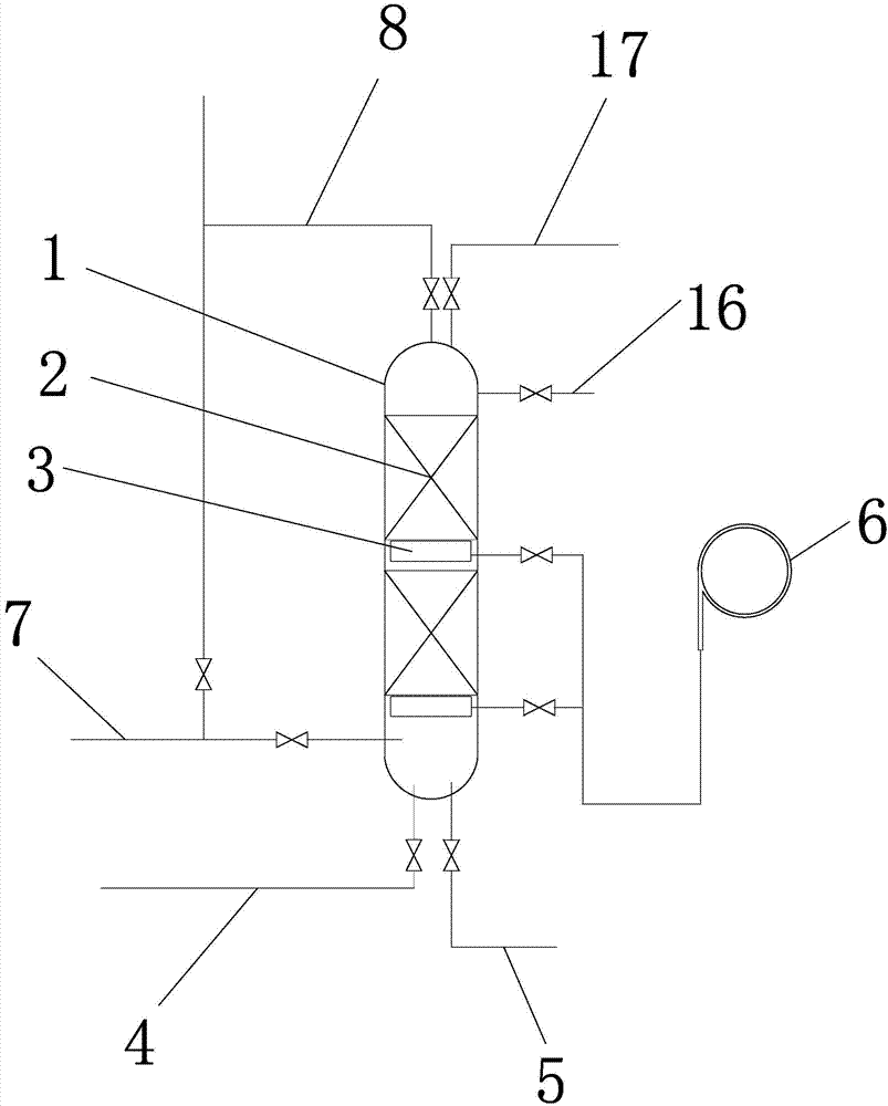
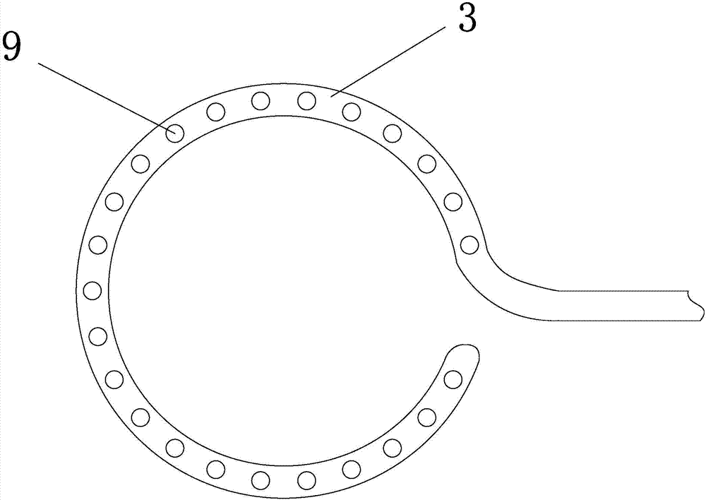
[0023] Embodiment 1: as figure 1 , 2As shown, a biological desulfurization tower packing flushing device, two packing layers 2 are longitudinally arranged inside the desulfurization tower 1, and there is a gap between the two packing layers, and the desulfurization tower 1 has a biogas inlet 7 and a biogas outlet 8, and a biogas inlet 7 It is located below the desulfurization tower 1 , and the biogas outlet 8 is located above the desulfurization tower 1 . An exhaust pipe 17 is installed on the top of the desulfurization tower 1 , a water inlet pipe 4 is installed under the desulfurization tower 1 , and a sewage discharge pipe 5 is installed at the bottom of the desulfurization tower 1 . A perforated aeration disc 3 is installed under each packing layer 2. The perforated aeration disc 3 is ring-shaped. One end of the perforated aeration disc 3 is sealed, and the other end is connected to the air source 6. The air source 6 is an air compressor. . Aeration holes 9 are arranged...

Embodiment 2

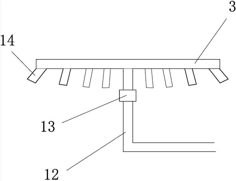
[0025] Embodiment 2: The structure of this embodiment is basically the same as that of Embodiment 1, the difference is that, as image 3 , 4 As shown, the perforated aeration disc includes a ring pipe 10, the gas source 6 is connected to the axis of the ring pipe 10 through a vertical axis pipe 12, and the axis of the ring pipe 10 is connected to the ring pipe through three rib pipes 11, The tendon tube 11 evenly surrounds the axis of the ring tube 10 . The axial center of the ring pipe 10 is connected with the vertical shaft pipe 12 through a pneumatic rotary joint 13 . The aeration hole 9 is located on the ring pipe 10, and the aeration hole 9 evenly surrounds the axis of the ring pipe 10. A guide sleeve 14 is installed on the aeration hole 9. The guide sleeve 14 is arranged obliquely and has an angle of 60° with the vertical plane. °. The upper surface of the perforated aeration disc 3 is attached to the lower surface of the packing layer 2 .

[0026] The gas from the g...

Embodiment 3

[0027] Embodiment 3: The structure of this embodiment is basically the same as that of Embodiment 2, the difference is that, as image 3 , 5 As mentioned above, the perforated aeration disc includes six bronchus 15, one end of the six bronchus 15 is sealed, and the other end is connected. The six bronchus 15 form a centrally symmetrical structure, and the air source passes through the vertical axis tube 12 and the symmetrical center of the bronchi. Connected, and the connection is a pneumatic rotary joint. The aeration holes are located on the same side of the bronchi, that is, they evenly surround the symmetrical center of the bronchi to form a centrosymmetric structure.

[0028] The gas from the gas source enters the symmetrical center of the six bronchi through the vertical shaft tube, fills the bronchi respectively, and then discharges from the aeration holes on the bronchi. Since the aeration holes are evenly distributed around the symmetrical center of the bronchus and...


PUM


Abstract

The invention relates to a biological desulfurization device for marsh gas and particularly relates to a washing device and a washing method for fillers of a biological desulfurization tower. The washing device for the fillers of the biological desulfurization tower is characterized in that a plurality of filler layers are arrayed in the desulfurization tower in the longitudinal direction; the washing device comprises a water inlet pipe, a blow-off pipe and perforated aeration discs, wherein the water inlet pipe is arranged below the desulfurization tower and the blow-off pipe is arranged at the bottom of the desulfurization tower; the perforated aeration discs are arranged below all the filler layers; the perforated aeration discs are connected with an air source; aeration holes are densely distributed below the perforated aeration discs. The washing device and the washing method for the fillers of the biological desulfurization tower have the beneficial effects that the filler layers can be effectively washed one by one so as to be prevented from being blocked; a desulfurization effect on the marsh gas by the filler layers is improved, the consumed time is short and the washing efficiency is improved, and furthermore, the efficiency of purifying the marsh gas is improved and the like.

Description

technical field [0001] The invention relates to a biogas biological desulfurization device, in particular to a biological desulfurization tower filler flushing device and a flushing method. Background technique [0002] There are several packing layers vertically arranged inside the existing biological desulfurization tower. The packing layer desulfurizes and purifies the biogas passing through the desulfurization tower. During the purification process, impurities such as elemental sulfur are formed in the packing layer. After long-term use, the packing layer is easy to be blocked. , thereby reducing the desulfurization effect of the packing layer on biogas. However, in the existing desulfurization tower, biogas can only pass through, and the packing layers cannot be cleaned one by one. If flushing is required, all packing layers need to be taken out one by one. The operation is cumbersome and time-consuming, which reduces the cleaning efficiency and further reduces the eff...

Claims


Application Information

Patent Timeline
IPC IPC(8): C10L3/10
CPCY02A50/20
Inventor 蔡昌达
Owner 杭州能源环境工程有限公司
Why Eureka
Try Eureka