Micro-miniature compressed air energy-storage system combining compressed air and hydraulic pressure

A technology of compressed air energy storage and compressed air, which is applied in the direction of steam engine devices, machines/engines, mechanical equipment, etc. It can solve problems such as harsh geographical conditions, not meeting the requirements of green energy development, and limiting the scope of application, etc., and the realization method is simple , constant pressure effect is remarkable, the effect of easy operation

Active Publication Date: 2014-02-12
HEFEI GENERAL MACHINERY RES INST
View PDF5 Cites 13 Cited by
  • Summary
  • Abstract
  • Description
  • Claims
  • Application Information

AI Technical Summary

Problems solved by technology

However, the traditional compressed air energy storage system still relies on burning fossil fuels to provide heat sources, which does not meet the requirements of green energy development; at the same time, it has strict requirements on the geographical conditions of the system construction sit

Method used


Image

  • Micro-miniature compressed air energy-storage system combining compressed air and hydraulic pressure

Examples


Embodiment Construction

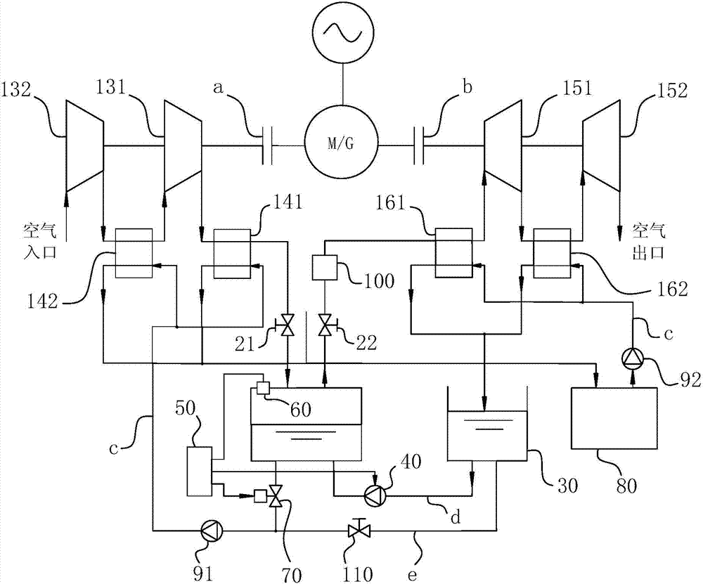
[0025] For ease of understanding, combined here figure 1 Concrete testing device of the present invention and operation process thereof are further described as follows:

[0026] In fact, the main pipeline layout of the system is initially divided by the inlet and outlet pipelines c and d on the liquid storage tank 30. The liquid outlet pipeline d of the liquid storage tank 30 is relatively simple, and only passes The pump 40 is enough to enter the gas storage tank 10; while the liquid inlet pipeline c of the liquid storage tank 30 is demarcated from the liquid outlet pipeline d by the gas storage tank 10, specifically through the flow control valve 70, the first A booster pump 91 and heat absorbers arranged in parallel enter into the high-temperature heat storage tank 80, and then flow from the high-temperature heat storage tank 80 into the liquid storage tank 30 through the heaters arranged in parallel to complete its overall pipeline structure. The supply line e is directl...


PUM


Abstract

The invention relates to the field of electric power energy-storage utilization, in particular to a micro-miniature compressed air energy-storage system combining compressed air and hydraulic pressure. The micro-miniature compressed air energy-storage system comprises a gas storage tank, a compressor unit and an expander unit, wherein energy conversion of both the compressor unit and the expander unit is achieved through a corresponding power generator or electric motor; a gas outlet of the compressor unit is communicated with a gas inlet of the gas storage tank, and a first switch part is arranged on a connecting pipeline between the gas inlet and the gas outlet; a gas inlet of the expander unit is communicated with a gas outlet of the gas storage tank, and a second switch part is arranged on a pipeline; the micro-miniature compressed air energy-storage system further comprises a liquid storage tank; a liquid inlet pipeline and a liquid outlet pipeline are arranged on the liquid storage tank and are communicated with the gas storage tank to form a circulatory liquid flow loop; and a pressurization and/or constant pressure component is arranged on the liquid inlet pipeline, and a hydraulic pump used for adding a liquid into the gas storage tank is arranged on the liquid outlet pipeline. The micro-miniature compressed air energy-storage system is high in energy conversion efficiency as well as reliable and stable in operation, has the advantages of low construction cost, high energy storage efficiency, good environmental adaptation and the like, and is broad in application prospect.

Description

technical field [0001] The invention relates to the field of electric energy storage utilization, in particular to a miniature compressed air energy storage system combining compressed air and hydraulic pressure. Background technique [0002] The unbalanced power load in the world is becoming increasingly prominent, and the peak-to-valley difference of the power grid is gradually widening. At the same time, people have higher and higher requirements for the power supply quality of the power grid. It is matched to alleviate the situation that the peak-to-valley difference of the system load is too large. Electric energy storage system is also an effective means to improve the utilization rate of renewable energy such as wind power and solar power. In addition, the power energy storage system is also a key technology to solve the problems of small capacity and large load fluctuation of distributed energy systems. [0003] Compressed air energy storage system is a recognized ...

Claims


Application Information

Patent Timeline
IPC IPC(8): F01K27/00
Inventor 杨启超赵远扬刘广彬王乐李连生
Owner HEFEI GENERAL MACHINERY RES INST
Why Eureka
Try Eureka