
A kind of oil sump of automobile engine

A technology of automobile engine and oil pan, which is applied in the direction of engine lubrication, engine components, machine/engine, etc., to reduce the difficulty of assembly and disassembly, improve the effect of cushioning and energy absorption, and reduce the workload

Active Publication Date: 2017-01-18
ZHEJIANG GEELY AUTOMOBILE RES INST CO LTD +1
View PDF8 Cites 0 Cited by
  • Summary
  • Abstract
  • Description
  • Claims
  • Application Information

AI Technical Summary

Problems solved by technology

[0005] The purpose of the present invention is to provide an oil pan of an automobile engine in view of the above-mentioned problems existing in the prior art. The technical problem to be solved by the present invention is to make the oil pan have a certain Softness, cushioning impact, reducing noise

Method used


Image

  • A kind of oil sump of automobile engine
  • A kind of oil sump of automobile engine
  • A kind of oil sump of automobile engine

Examples


Embodiment 1

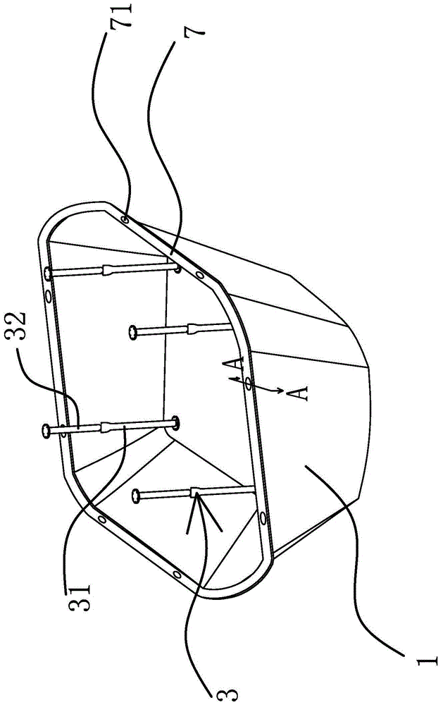
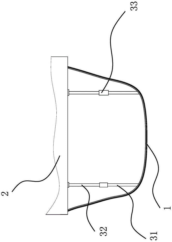
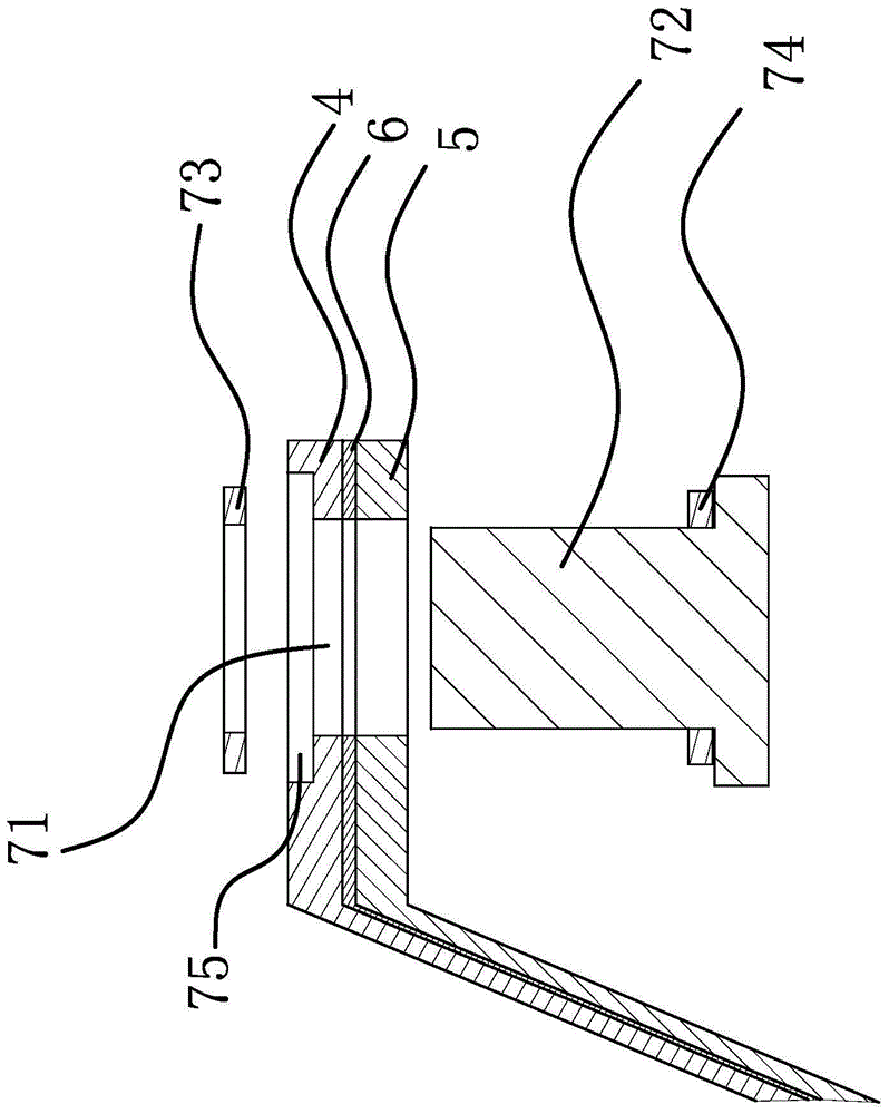
[0030] Such as figure 1 , figure 2 , Figure 4 and Figure 5 Shown, a kind of oil pan of automobile engine, this oil pan comprises a flexible shell 1 that is connected at the lower end of engine block 2, and the upper end of shell 1 is connected with the lower end of engine block 2, and the bottom of shell 1 Also be provided with a support structure 3 that can support the bottom of the housing 1 between the bottom and the engine block 2, the support structure 3 includes several support rods 31 that are fixedly connected at the bottom of the housing 1 and are fixed with the engine block 2. Connected support rod two 32, a living hinge 33 is arranged between the upper end of the support rod one 31 and the lower end of the support rod two 32, and the basic shape and size of the housing 1 are kept in the process of automobile bumping and mechanical vibration, and the living hinge 33 A degree of freedom in the horizontal direction can be provided for the shell 1, so that the she...

Embodiment 2

[0034] Such as Figure 6 As shown, the content of this embodiment is roughly the same as that of Embodiment 1, except that the support structure 3 includes several elastic metal strips 34, and the two ends of the metal strips 34 are fixedly connected to the bottom of the housing 1 and the cylinder body 2 respectively. , the elastic metal strip 34 can maintain the basic shape and size of the shell 1, and can elastically deform when an impact occurs, so that the shell 1 can be cushioned, and the metal strip 34 can also restore the shell after the shell 1 is impacted 1 for the original shape.

[0035] The working principle of the present invention is: in order to improve the shape of the oil pan with traditional rigid structure, which has poor cushioning effect and is prone to rupture when it is hit, the shell 1 of the oil pan of the engine is made of flexible material. Through the local deformation of the housing 1, it can have a good buffering effect. In order to maintain the ...


PUM

PropertyMeasurementUnit
thicknessaaaaaaaaaa
thicknessaaaaaaaaaa
thicknessaaaaaaaaaa

Abstract

The invention provides an oil pan of an automobile engine, and belongs to the technical field of automobiles. The oil pan solves the technical problem that an existing engine oil pan does not have good buffering or energy absorption effect. The oil pan of the automobile engine comprises a flexible shell connected to the lower end of an engine cylinder body, the upper end of the shell is fixedly connected with the lower end of the engine cylinder body, and a supporting structure capable of supporting the bottom of the shell is further arranged between the bottom of the shell and the engine cylinder body. The oil pan of the automobile engine has the advantages of having good buffering and energy absorption effects while being impacted and the like.

Description

technical field [0001] The invention belongs to the technical field of automobiles, and relates to an oil pan, in particular to an oil pan of an automobile engine. Background technique [0002] The oil pan is located at the lower part of the engine and can be disassembled to seal the crankcase as an oil storage tank. The oil sump is the lower half of the crankcase, also known as the lower crankcase. Its function is to close the crankcase as the outer shell of the oil storage tank, prevent impurities from entering, and collect and store the lubricating oil that flows back from the friction surfaces of the engine. Part of the heat prevents the lubricating oil from oxidizing. [0003] At present, the oil pan of automobile engines is generally made of metal materials, and the structure is fixed. When it is hit by the outside world, the oil pan is easy to break, and oil leakage occurs, which causes the engine to scuff due to lack of oil lubrication. In severe cases The engine i...

Claims


Application Information

Patent Timeline
Patent Type & Authority Patents(China)
IPC IPC(8): F01M11/00B32B27/06B32B25/04B32B25/10F16F15/06
Inventor 谢汶桦康世邦刘岩沈源由毅吴成明冯擎峰
Owner ZHEJIANG GEELY AUTOMOBILE RES INST CO LTD
Learn More