
Inlet and exhaust port structure and optimization method of low speed engine cylinder head

A technology for engine cylinders and exhaust passages, applied in the direction of engine components, machines/engines, cylinder heads, etc., can solve the problems of poor airflow, affecting combustion rate and efficiency, etc., to improve airflow organization, increase combustion rate, The effect of increasing air speed

Inactive Publication Date: 2016-12-07
重庆全景通用动力机械有限公司
View PDF9 Cites 0 Cited by
  • Summary
  • Abstract
  • Description
  • Claims
  • Application Information

AI Technical Summary

Problems solved by technology

At present, low-speed engines are widely used because of their large torque and easy starting. The existing low-speed engine intake and exhaust passages are designed to cause poor flow of air, which greatly affects the combustion rate and efficiency.

Method used


Image

  • Inlet and exhaust port structure and optimization method of low speed engine cylinder head
  • Inlet and exhaust port structure and optimization method of low speed engine cylinder head
  • Inlet and exhaust port structure and optimization method of low speed engine cylinder head

Examples


Embodiment Construction

[0028] Below in conjunction with accompanying drawing and embodiment the present invention will be further described:

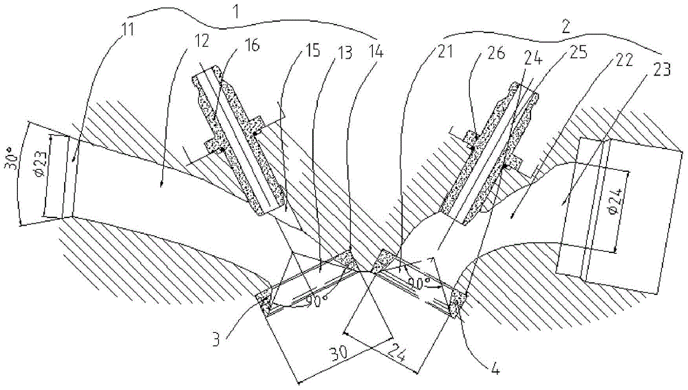
[0029] like figure 1 The intake and exhaust duct structure of a cylinder head of a low-speed engine shown includes an intake duct 1 and an exhaust duct 2 arranged on the cylinder head, and the intake duct 1 is formed by an intake section 11 1. The inlet transition section 12 and the air outlet section 13 of the inlet are connected in sequence, wherein the inlet section 11 of the inlet is a bell mouth with a large diameter outside and a small inside, and the air outlet section 13 of the inlet is a small diameter inside. Large bell mouth, and the diameter of the small-diameter end of the air inlet section 11 of the air inlet is greater than the diameter of the small-diameter end of the air outlet section 13 of the air inlet, and the air inlet section 11 of the air inlet and the transition section 12 of the air inlet The connection is a smooth transition, and t...


PUM


Abstract

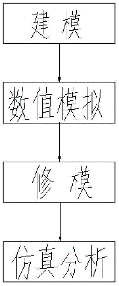
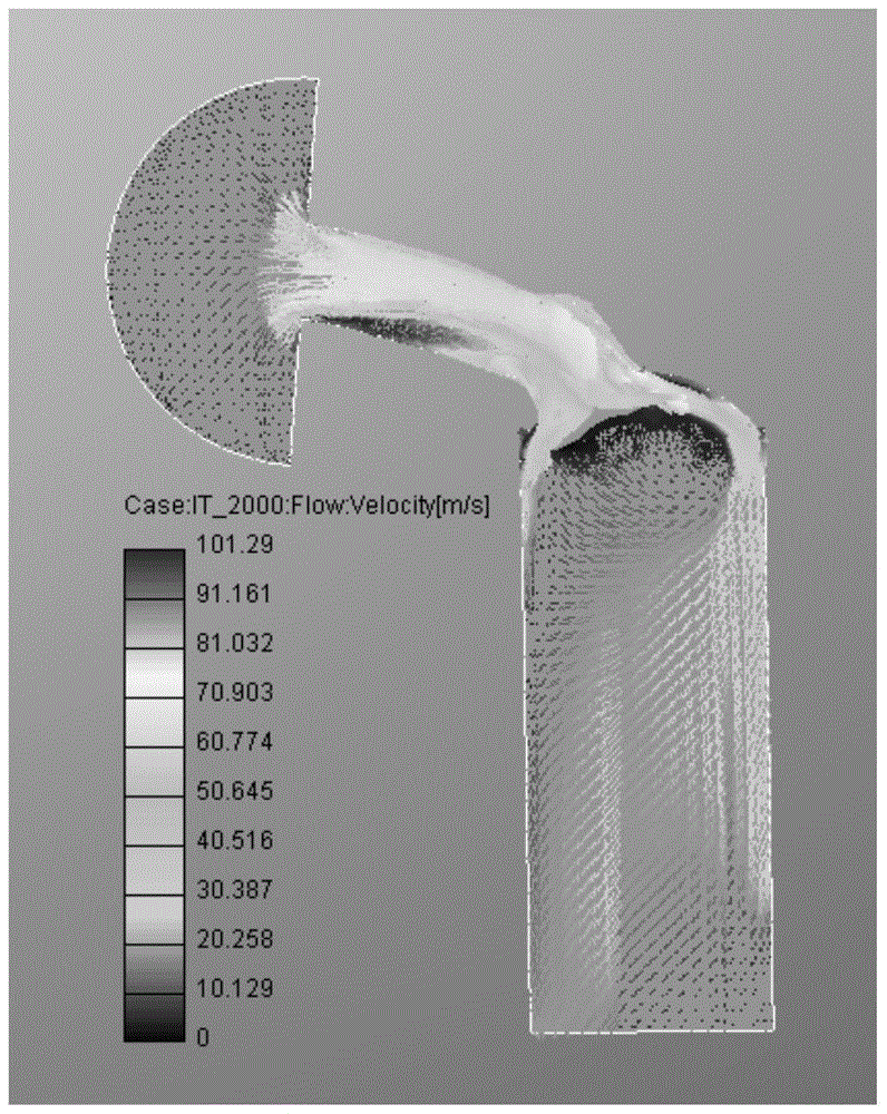
The invention discloses a low-speed engine cylinder cover air inlet and exhaust duct structure and an optimization method of the low-speed engine cylinder cover air inlet and exhaust duct structure. The center position of an air inlet and the center position of an air outlet are unchanged, only the diameter of an inlet pipe and the diameter of an outlet pipe are changed, namely, the diameter of an air inlet duct air inlet section, the diameter of an air inlet duct air outlet section, the diameter of an air exhaust duct air inlet section and the diameter of the air exhaust duct air outlet section are changed, an air inlet duct and an air exhaust duct are optimized through modeling, numerical simulation, model repairing, simulated analysis and other steps, air duct flow direction molded lines are smooth as much as possible, the diameter of the air inlet duct and the diameter of the air exhaust duct are reduced to reasonable numerical values, the flow velocity of air flowing through the air ducts is increased, the rolling flow ratio in a combustor is increased, and the combustion speed is increased.

Description

technical field [0001] The invention belongs to the technical field of engines, and in particular relates to a low-speed engine cylinder head intake and exhaust duct structure and an optimization method thereof. Background technique [0002] The intake and exhaust passages are the final link between the intake and exhaust system and the engine. High-speed engines and low-speed engines have different requirements for intake and exhaust passages. For high-speed air passages, we hope to obtain greater air passage flow, while for low-speed air passages, due to the low airflow velocity, we hope to increase airflow speed at low speeds, improve airflow organization, strengthen in-cylinder flow, and increase combustion rate. At present, low-speed engines are widely used because of their large torque and easy starting. The existing low-speed engine intake and exhaust passages cause poor flow of air due to design reasons, thereby greatly affecting combustion rate and efficiency. Con...

Claims


Application Information

Patent Timeline
Patent Type & Authority Patents(China)
IPC IPC(8): F02F1/42
Inventor 王敬王勇王腾周敏邢峰曹建国
Owner 重庆全景通用动力机械有限公司
Learn More