Electromagnetic spool valve

A sliding valve, electromagnetic technology, applied in valve details, valve device, valve housing structure, etc., can solve problems such as sliding wear or sliding defects

Inactive Publication Date: 2014-02-12
DENSO CORP
View PDF7 Cites 9 Cited by
  • Summary
  • Abstract
  • Description
  • Claims
  • Application Information

AI Technical Summary

Problems solved by technology

Foreign objects reaching high magnetic flux density parts may be involved in sliding wear or sliding defects in the plunger

Method used


Image

  • Electromagnetic spool valve
  • Electromagnetic spool valve
  • Electromagnetic spool valve

Examples


no. 1 example

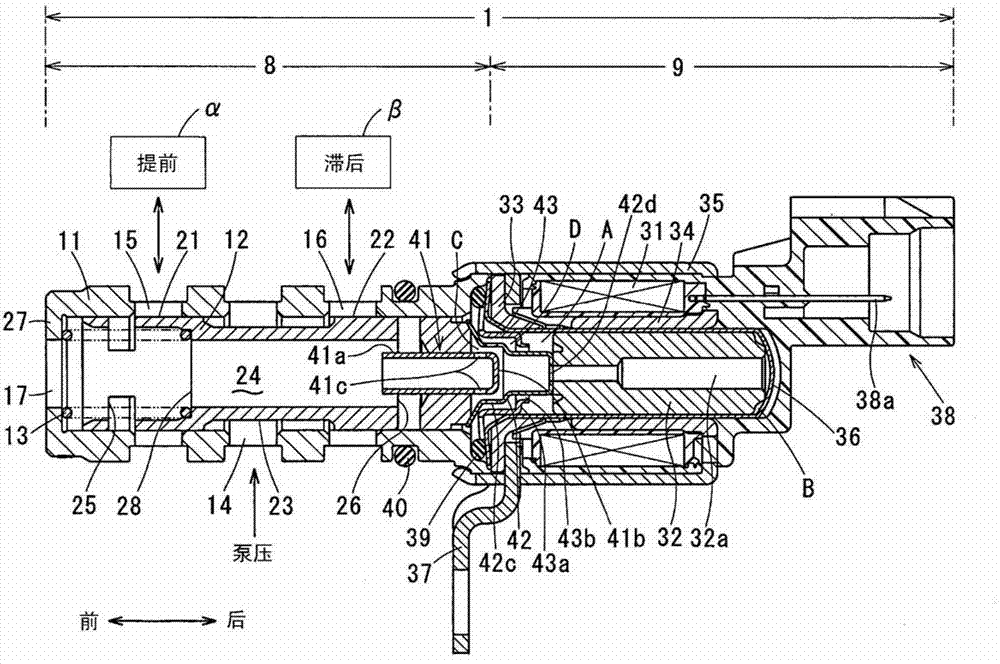
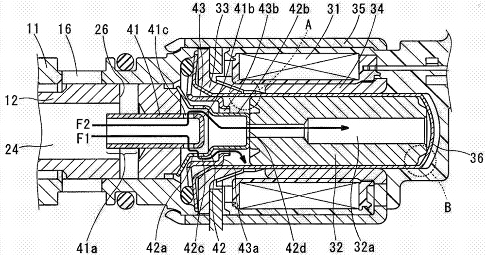
[0017] will combine Figure 1 to Figure 3 The first embodiment is explained. This embodiment is aimed at the OCV (Oil Control Valve) of the hydraulic VVT (Variable Valve Timing).

[0018] (Explanation of VVT)
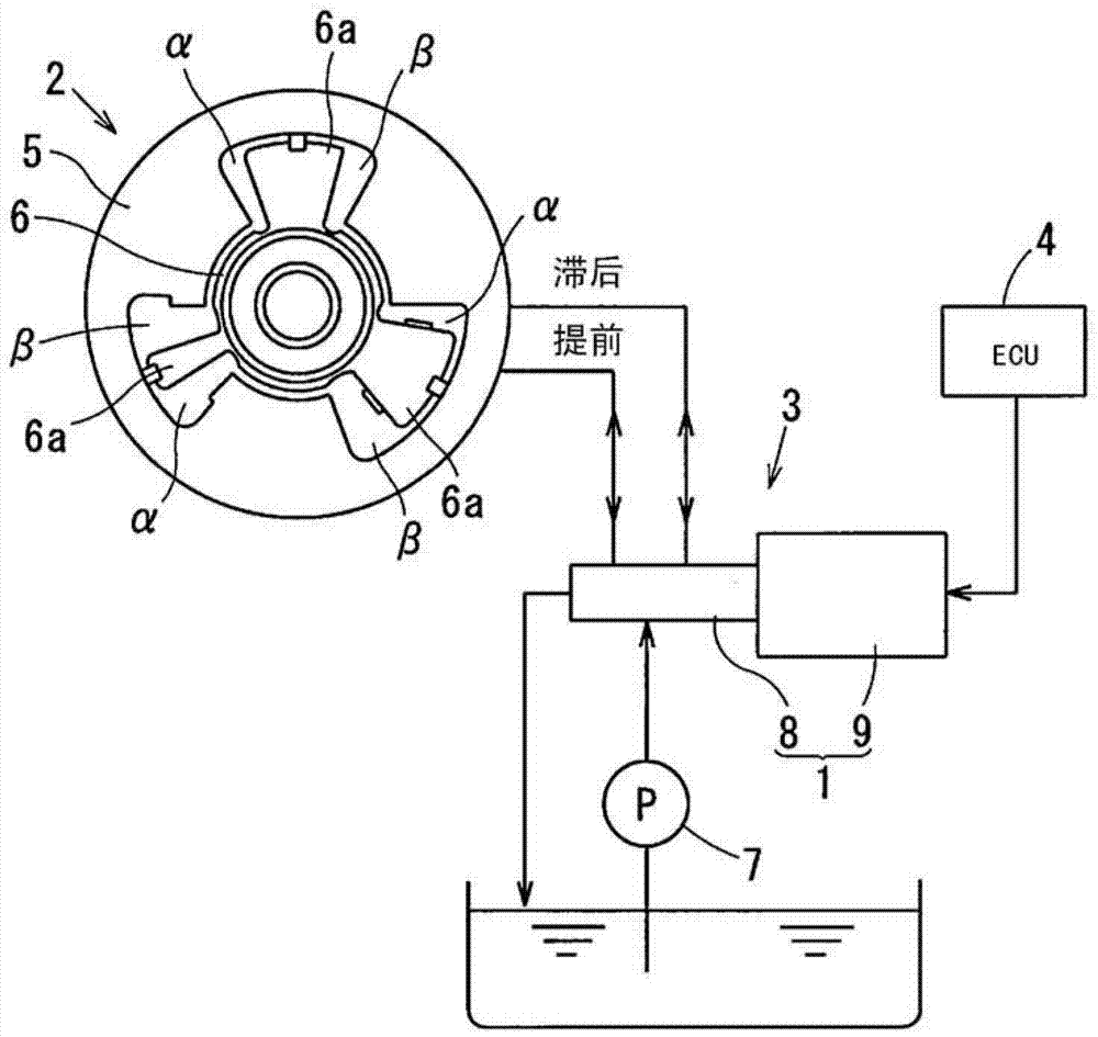
[0019] The VVT ​​is installed in an engine for running a vehicle. VVT includes: (i) VCT (Variable Camshaft Timing Mechanism) 2, which is attached to the camshaft so as to steplessly change the advance angle of the camshaft and thus steplessly change the opening and closing timing of the valve; (ii) is performed using OCV1 Hydraulic circuit 3 for hydraulic control of VCT2; and (iii) ECU (Engine Control Unit) 4 for electrically controlling OCV1.

[0020] The VCT 2 includes a shoe housing 5 that rotates synchronously with a crankshaft of the engine, and a vane rotor 6 that rotates integrally with a camshaft. Driving the vane rotor 6 relative to the shoe housing 5 allows the camshaft to be changed on the advanced angle side or the retarded angle side.

[0021] The vane...

no. 2 example

[0073] will be combined as follows Figure 4 The second embodiment is explained. The first embodiment provides an example in which the first space C and the in-plunger breathing hole 32a communicate with each other via the axial hole 42d. Alternatively, the second embodiment eliminates the axial hole 42d, and allows the high magnetic flux density portion A to communicate with the in-plunger breathing hole 32a.

[0074] Specifically, the rear end of the hollow shaft 42 is blocked; the radial recess 42e is disposed on the back of the hollow shaft 42; and the radial recess 42e extends radially. The high magnetic flux density portion A and the in-plunger breathing hole 32a communicate with each other via the radial recess 42e. This prevents foreign matter from reaching the low magnetic flux density portion B more surely.

[0075] The above embodiments provide the sleeve 11; alternatively, the spool valve 8 may be designed without the sleeve 11. That is, the spool 12 can be ins...


PUM


Abstract

Drain oil is discharged into an oil drain passage from an advance angle port and discharge port, or from a delay angle port and discharge port; the drain oil may be mixed with foreign matter. The flow of such foreign matter accompanying the drain oil, even if flowing toward an electromagnetic actuator, can be hindered from reaching a high magnetic flux density portion by each of a pipe, a hollow shaft, and a collar. The high magnetic flux density portion, which is easy to be affected by influence of the foreign matter, can be prevented from suffering from the arrival of the foreign matter; this prevents an occurrence of the slide abrasion and/or the slide defect of a plunger, improving the reliability of an oil control valve.

Description

technical field [0001] The present invention relates to an electromagnetic spool valve which combines a spool valve and an electromagnetic actuator (linear solenoid) in the axial direction; in particular, it relates to an electromagnetic spool valve in which two shafts facing the plunger in the axial direction The side space gaps each communicate with the discharge space via the interior of the spool. Background technique [0002] [Patent Document 1] JP2003-97756A [0003] Patent Document 1 describes an electromagnetic spool valve in which space gaps facing both sides in the axial direction of the plunger each communicate with a discharge space via an oil discharge passage inside the spool. The electromagnetic spool valve combines the spool valve and the electromagnetic actuator in the axial direction, and has an oil discharge passage (a passage hole in the axial direction) located in the middle of the spool, and the oil discharge passage communicates with the discharge spa...

Claims


Application Information

Patent Timeline
Patent Type & Authority Applications(China)
IPC IPC(8): F16K31/06
CPCF16K27/048F16K31/0613F16K31/0675Y10T137/86694F16K31/0603
Inventor 近藤二郎
Owner DENSO CORP
Why Eureka
Try Eureka