
An overcurrent detection circuit and method for a power switch tube

A power switch tube, overcurrent detection technology, applied in circuits, measuring electricity, measuring electrical variables and other directions, can solve problems such as reducing amplifier gain, and achieve the effect of increasing gain

Active Publication Date: 2016-03-23
FAIRCHILD SEMICON SUZHOU
View PDF7 Cites 0 Cited by
  • Summary
  • Abstract
  • Description
  • Claims
  • Application Information

AI Technical Summary

Problems solved by technology

figure 2 When the positive and negative input voltages of the amplifier shown are close to or equal to the power supply voltage, the drain and source voltages of NMOSN21 are very close, making NMOSN21 work in the linear region and reducing the gain of the amplifier

Method used


Image

  • An overcurrent detection circuit and method for a power switch tube
  • An overcurrent detection circuit and method for a power switch tube
  • An overcurrent detection circuit and method for a power switch tube

Examples


Embodiment Construction
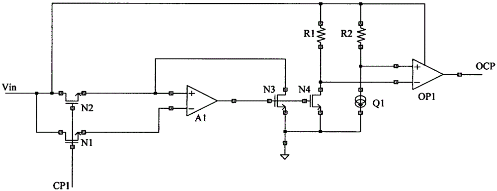
[0024] The basic idea of ​​the present invention is: the sampling circuit uses the sampling MOS tube and the amplifier to sample the current of the power switch tube, converts the sampling current into the sampling voltage and transmits it to the comparison circuit, and connects the clamp MOS tube in series to the output terminal of the amplifier The working voltage of the circuit and the comparison circuit are clamped; the comparison circuit compares the size of the sampling voltage and the reference voltage, and outputs the overcurrent detection result.

[0025] Hereinafter, the present invention will be further described in detail through the drawings and specific embodiments.

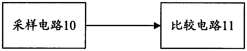
[0026] The present invention realizes an overcurrent detection circuit of a power switch tube, such as image 3 As shown, the overcurrent detection circuit of the power switch tube includes: a sampling circuit 10 and a comparison circuit 11; wherein,

[0027] The sampling circuit 10 is configured to use a ...


PUM


Abstract

The invention discloses an overcurrent detection circuit of a power switch tube. The sampling circuit of the overcurrent detection circuit uses a sampling MOS tube and an amplifier to sample the current of the power switch tube, converts the sampling current into a sampling voltage and transmits it to a comparison circuit, and The operating voltage of the output circuit of the amplifier and the comparison circuit is clamped by connecting the clamp MOS tube in series; the comparison circuit compares the magnitude of the sampling voltage and the reference voltage, and outputs the overcurrent detection result; the invention also discloses An overcurrent detection method of a power switch tube, through the scheme of the present invention, the overcurrent detection of the power switch tube can be realized, so that the output terminal circuit and the comparison circuit of the amplifier in the sampling circuit can be composed of low-voltage devices, and the amplifier can also be A structure in which the PMOS source of the current mirror is used as the input terminal, and the gate voltage of the NMOS at the output terminal is clamped by the PMOS can effectively increase the gain of the amplifier.

Description

Technical field [0001] The invention relates to current detection technology, in particular to an overcurrent detection circuit and method of a power switch tube. Background technique [0002] The power switch tube is a power metal oxide semiconductor field effect transistor (MOS), and its turn-on and turn-off characteristics are usually used to realize high-efficiency conversion of signals and energy such as switching power supplies, switching amplifiers, and charge pumps. When the power MOS tube is turned on, a relatively large current usually flows. If the circuit flowing through exceeds the withstand limit of the power MOS tube, the power MOS tube may be permanently damaged. Therefore, in order to ensure the reliability of the power MOS tube, the current flowing through the power MOS tube must be continuously detected, and the power MOS tube can be over-current protected when the current flowing through is too large. [0003] figure 1 An N-type metal oxide semiconductor field ...

Claims


Application Information

Patent Timeline
Patent Type & Authority Patents(China)
IPC IPC(8): G01R19/165
CPCG01R19/16519H01L27/0285H03K17/0822G01R19/165G01R31/2621
Inventor 黄雷
Owner FAIRCHILD SEMICON SUZHOU
Features
  • Generate Ideas
  • Intellectual Property
  • Life Sciences
  • Materials
  • Tech Scout
  • Unparalleled Data Quality
  • Higher Quality Content
  • 60% Fewer Hallucinations
Learn More