
A 3D Imaging Method of Precessing Cone

A 3D imaging and cone technology, applied in the field of signal processing, can solve problems such as moving over distance units, failure of 2D image calibration methods, etc.

Active Publication Date: 2015-09-09
XIDIAN UNIV
View PDF6 Cites 0 Cited by
  • Summary
  • Abstract
  • Description
  • Claims
  • Application Information

AI Technical Summary

Problems solved by technology

However, this method requires that the change in the rotational angular velocity of the target relative to the radar is less than 0.05rad / s, and the total rotational angle is less than 360°, while the precessing target rotates at a high speed during the observation time, the total rotational angle will exceed 360°, and the precessing cone target Scattering centers will have serious over-distance cell movement, which will invalidate the two-dimensional image calibration method based on fractional Fourier transform; when the target contains sliding scattering centers or there is occlusion, the scattering centers cannot be completely matched and the three-dimensional scattering centers will be relocated. struct method failure

Method used


Image

  • A 3D Imaging Method of Precessing Cone
  • A 3D Imaging Method of Precessing Cone
  • A 3D Imaging Method of Precessing Cone

Examples


Embodiment Construction

[0072] In order to make the above-mentioned and other objects, features and advantages of the present invention more obvious, the following specific embodiments of the present invention are given and described in detail in conjunction with the accompanying drawings. Many specific details are set forth in the following description to facilitate a full understanding of the present invention, but the present invention can also be implemented in other ways different from those described herein, and those skilled in the art can do so without departing from the connotation of the present invention. Similar promotion, therefore, the present invention is not limited by the specific embodiments disclosed below.

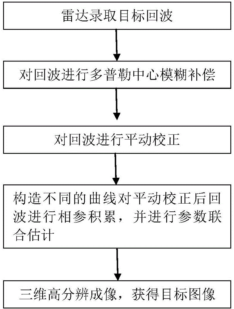
[0073] refer to figure 1 , figure 1Be the flow chart of the inventive method, the inventive method comprises the following steps:

[0074] Step 1. The radar transmits and receives pulses at the pulse repetition frequency, and records the target echoes in the digital solution...


PUM


Abstract

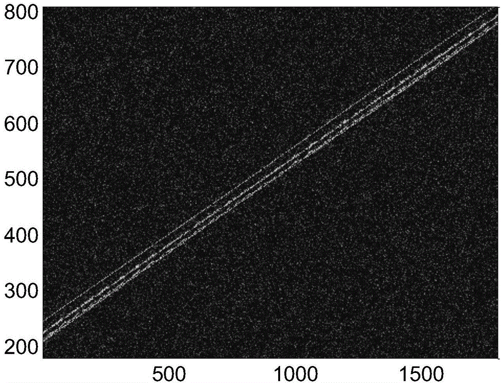
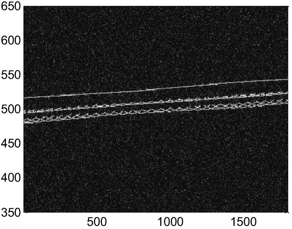
The invention provides a method for three-dimensional imaging of a precession cone. The method comprises the following steps that pulses are transmitted and received by radar at the pulse repetition rate and an echo with the distance serving as a row vector and with the orientation serving as a column vector is obtained; Doppler central fuzzy compensation is conducted on the echo and an echo of a distance frequency domain-orientation slow time domain is obtained after compensation is conducted; translational motion correction is conducted on the echo through a time domain scale variation method; different curves are constructed, phase-coherent accumulation is conducted on the echo after translational motion is conducted, joint estimation is conducted on jogging parameters, three-dimensional coordinates are marked according to three-dimensional images of other scattering centers and a three-dimensional image of a conic vertex scattering center, three-dimensional imaging is conducted, and a three-dimensional image of a precession cone target is obtained. According to the method for three-dimensional imaging of the precession cone, the scattering center distribution feature of a precession cone optical zone is utilized, the real three-dimensional coordinates of the cone scattering center are estimated, accurate estimation of the jogging parameters such as a conic precession angle is achieved, and therefore the three-dimensional image with good focusing and high resolution of the complex precession cone target is obtained.

Description

technical field [0001] The invention belongs to the technical field of signal processing, and in particular relates to a high-resolution three-dimensional imaging method of a precession cone in the radar signal processing technology. Background technique [0002] Precession is a typical fretting form of space targets such as cones. If the three-dimensional distribution of the scattering center of the precession cone and the micro-motion parameters such as spin frequency, precession frequency, and precession angle can be accurately estimated through high-resolution radar imaging, the shape, structure and motion information of such targets can be obtained. It provides important support for subsequent target classification and identification. At present, high-resolution imaging and micro-motion parameter estimation of typical micro-moving targets are important research directions in the fields of radar imaging and radar automatic target recognition. [0003] The Chinese inven...

Claims


Application Information

Patent Timeline
Patent Type & Authority Patents(China)
IPC IPC(8): G01S7/41G01S7/32
CPCG01S7/40G01S13/89
Inventor 白雪茹周峰刘妍保铮
Owner XIDIAN UNIV
Learn More