Eureka AIR delivers breakthrough ideas for toughest innovation challenges, trusted by R&D personnel around the world.

Synthetic aperture sonar imaging method and system based on multidimensional waveform encoding

A synthetic aperture sonar and waveform coding technology, applied in radio wave measurement systems, re-radiation of sound waves, utilization of re-radiation, etc. The effect of improving surveying efficiency

Inactive Publication Date: 2014-02-12
INST OF ACOUSTICS CHINESE ACAD OF SCI
View PDF1 Cites 7 Cited by
  • Summary
  • Abstract
  • Description
  • Claims
  • Application Information

AI Technical Summary

Problems solved by technology

[0004] In the field of Synthetic Aperture Radar (SAR), in order to improve the mapping bandwidth of spaceborne SAR and break through the limit of mapping efficiency caused by traditional distance and azimuth ambiguity, in the 1990s, a DPCA system using a multi-phase center was proposed. , only improves the receiving aperture in the receiving aspect, and lacks the method of increasing the transmitting power to increase the power-aperture product
With the improvement of resolution, some new technologies have emerged, such as time-sharing transmission and time-sharing reception, which have lower requirements on the hardware system, but there is a problem of sub-pulse and distance coupling, which affects the quality of the image
therefore, like SAR, single-shot based SAR systems also suffer from the problem of obtaining high power aperture products and large signal bandwidths

Method used


Image

  • Synthetic aperture sonar imaging method and system based on multidimensional waveform encoding
  • Synthetic aperture sonar imaging method and system based on multidimensional waveform encoding
  • Synthetic aperture sonar imaging method and system based on multidimensional waveform encoding

Examples


Embodiment Construction

[0022] The synthetic aperture sonar based on the azimuth multi-dimensional waveform coding of the present invention will be described in detail below with reference to the accompanying drawings.

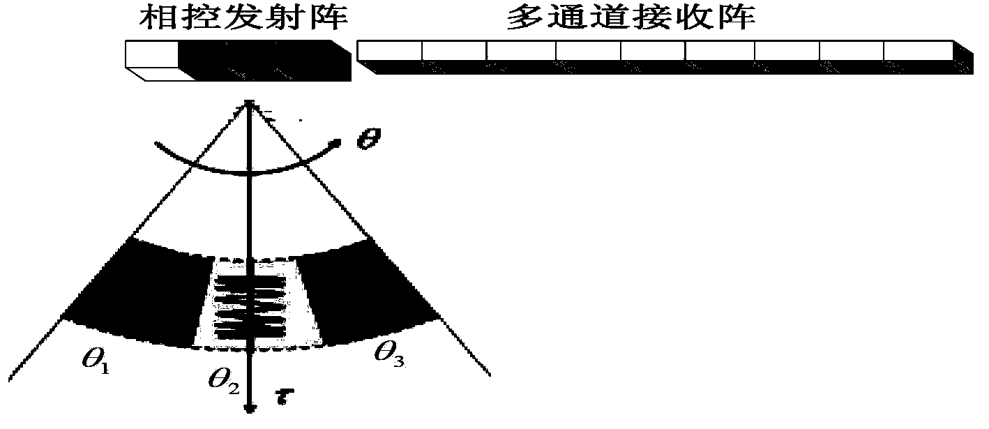
[0023] 1. First, at the transmitting end, the transmitting array of the synthetic aperture sonar is phase-controlled and the central angle is θ 1 ,…,θ L Narrow beam signals of different carrier frequencies, and the pulse width T corresponding to the transmitted signal of the transmitting array p Divided into L sub-pulses, the time width of each sub-pulse is T pl , using transmit beamforming to control the beam pointing in different sub-pulse time widths to illuminate different sub-swaths. This imaging method using space diversity technology can obtain more equivalent phase centers in one pulse repetition period, so that the surveying and mapping efficiency is improved. Such as figure 1 As shown, the system is composed of a phase-controlled transmitting array and a multi-channel r...


PUM


Abstract

The invention designs a synthetic aperture sonar imaging method and a system based on multidimensional waveform encoding, and the method is based on multidimensional waveform encoding of a time domain, a space domain and a frequency domain of an azimuth. The method comprises: a step 101) a sending array sends multiple central angles and narrow wave beam signals with different carrier frequencies via phased strategies, the sent pulse time width is divided into multiple sub-pulses, and the sent wave beams are utilized to form strategy control wave beam indications in different sub-pulse periods of time so that the strategy control wave beam indications irradiate different sub-surveying-and-mapping bands; and a step 102) Pulse compression and azimuth FFT are respectively performed on multi-aperture data of each surveying-and-mapping band received by a multichannel receiving array, then azimuth spatial filtering is performed according to an ambiguity-resolving mode, and then focusing imaging is performed by adopting an imaging algorithm. To sum up, the technical scheme adopts a spatial diversity technology, and more azimuth spatial samplings can be obtained in one pulse repetition period so that surveying-and-mapping efficiency is enhanced. The synthetic aperture sonar imaging method and the system are mainly applied to the field of underwater acoustic imaging.

Description

technical field [0001] The invention belongs to the field of underwater acoustic imaging and sonar signal processing. The present invention designs a synthetic aperture sonar imaging method based on azimuth multi-dimensional waveform coding. The method adopts space diversity technology and can obtain more azimuth space sampling within one pulse repetition period, thereby improving surveying and mapping efficiency. In particular, it relates to a synthetic aperture sonar imaging method and system based on multi-dimensional waveform coding. Background technique [0002] Synthetic Aperture Sonar (SAS) is an advanced high-resolution underwater acoustic imaging sonar. The nano-echoes are coherently processed to obtain high resolution in azimuth. [0003] The imaging efficiency of high-resolution imaging sonar is one of the decisive factors that determine whether sonar can be used in practice. For example, in the actual operation of traditional synthetic aperture sonar, under th...

Claims


Application Information

Patent Timeline
Patent Type & Authority Applications(China)
IPC IPC(8): G01S15/89
CPCG01S7/52015G01S7/524G01S15/8904
Inventor 段江涛黄勇刘纪元
Owner INST OF ACOUSTICS CHINESE ACAD OF SCI
Why Eureka
Eureka Blog
Learn More