
Optical measurement device and vehicle

A technology of optical measurement equipment and vehicles, which is applied in the direction of optical radiation measurement, measuring device, measuring distance, etc., and can solve the problems of blurred object points and inability to obtain resolution, etc.

Active Publication Date: 2014-02-12
RICOH KK
View PDF6 Cites 28 Cited by
  • Summary
  • Abstract
  • Description
  • Claims
  • Application Information

AI Technical Summary

Problems solved by technology

However, in this case, in the angular space of each object point (for the projection optical system, the divergence angle of the semiconductor laser as the light source or the effective range of the transmitter lens; for the receiving optical system, the effective range of the receiver lens) , especially near the device, the object point is blurred and the desired resolution cannot be obtained

Method used


Image

  • Optical measurement device and vehicle
  • Optical measurement device and vehicle
  • Optical measurement device and vehicle

Examples


Embodiment Construction

[0028] Hereinafter, embodiments of the present invention are explained with reference to the drawings. In these drawings, corresponding elements may be denoted by the same reference numerals, and repeated explanation may be omitted.

[0029] In this application, the optical measurement device includes, for example, a device that irradiates light to a predetermined area and determines whether an object exists in the predetermined area based on reflected light or scattered light. Also, in this application, the optical measuring device includes, for example, a device that, when it is determined that an object exists in a predetermined area, irradiates light to the object and measures a distance to the object based on reflected light or scattered light.

[0030]

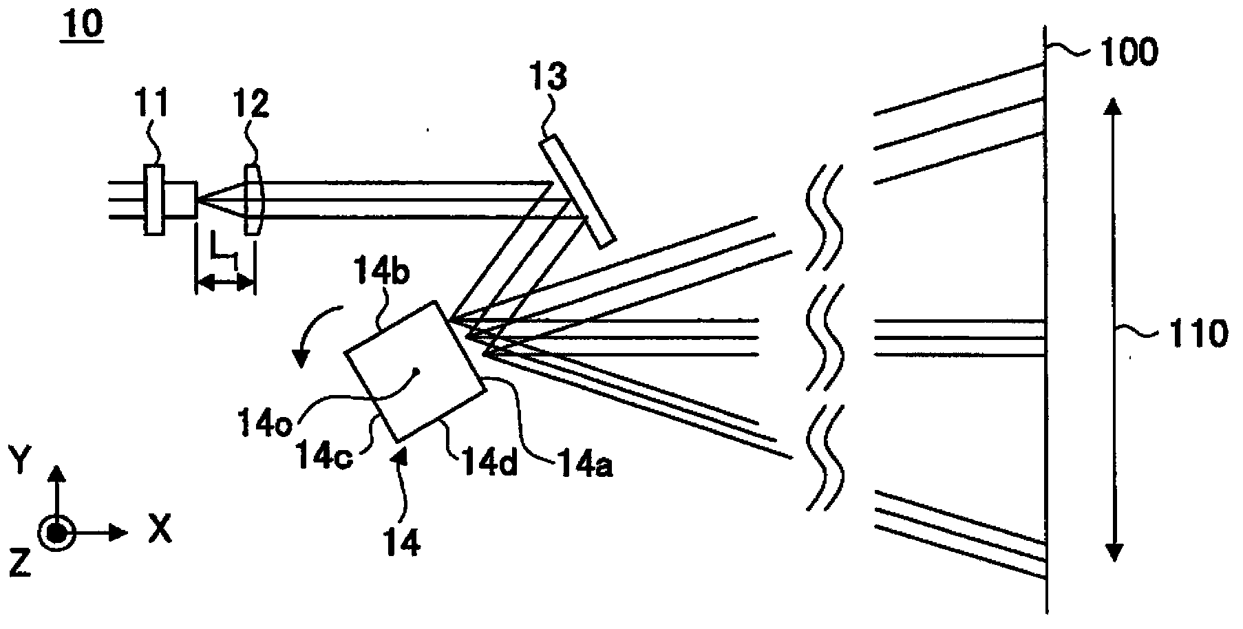
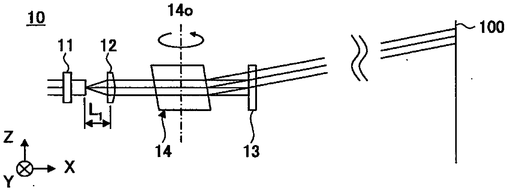
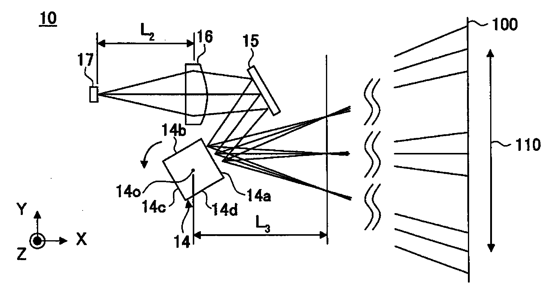
[0031] Figure 1A and 1B is a schematic diagram illustrating a projection optical system of an optical measurement device according to an example. Figure 1A A cross section in a direction parallel to the XY-plane is ...


PUM


Abstract

Disclosed is an optical measurement device including a first light source, an optical element that condenses a light beam emitted from the first light source, a light irradiator that irradiates the light beam onto an object; and a photo detector that detects reflected light or scattered light of the light beam from the object through an imaging system, the light beam being irradiated onto the object, wherein a first optical path length from the first light source to a first conjugate image of the first light source by the optical element is different from a second optical path length from the photo detector to a second conjugate image of the photo detector by the imaging system at least in a first direction.

Description

technical field [0001] The present invention relates to an optical measuring device and a vehicle on which the optical measuring device is installed. The optical measuring device detects the presence of an object and measures the distance from the optical measuring device to the object. For safety reasons, this optical measuring device can be used in factory automation (FA), or for automotive use. Background technique [0002] Optical measuring devices are known which detect the presence of an object and measure the distance to the object. As an example of an optical measuring device, the following device can be considered. That is, the apparatus scans a predetermined measurement field with the light beam by deflecting the light beam by a rotating polygon mirror. This device receives the light reflected by the object to be measured in the measurement field with a photodetector by continuously changing the viewing angle using the same rotating polygonal mirror, and thus me...

Claims


Application Information

Patent Timeline
Patent Type & Authority Applications(China)
IPC IPC(8): G01V8/10G01S17/08G01S17/931
CPCG01S17/08G01S17/936G01J1/0422G01C3/08G01S7/4812G01S7/4817G01S17/10G01S17/42G01S7/4811G01S7/4815G01S17/931
Inventor 仲村忠司今井重明
Owner RICOH KK
Learn More