
Liquid heating apparatus

A liquid heater and equipment technology, which can be used in beverage preparation devices, kitchen utensils, home utensils, etc., and can solve problems such as waste

Inactive Publication Date: 2014-02-12
STRIX LTD
View PDF9 Cites 10 Cited by
  • Summary
  • Abstract
  • Description
  • Claims
  • Application Information

AI Technical Summary

Problems solved by technology

All these features are also wasteful

Method used


Image

  • Liquid heating apparatus
  • Liquid heating apparatus
  • Liquid heating apparatus

Examples


Embodiment Construction

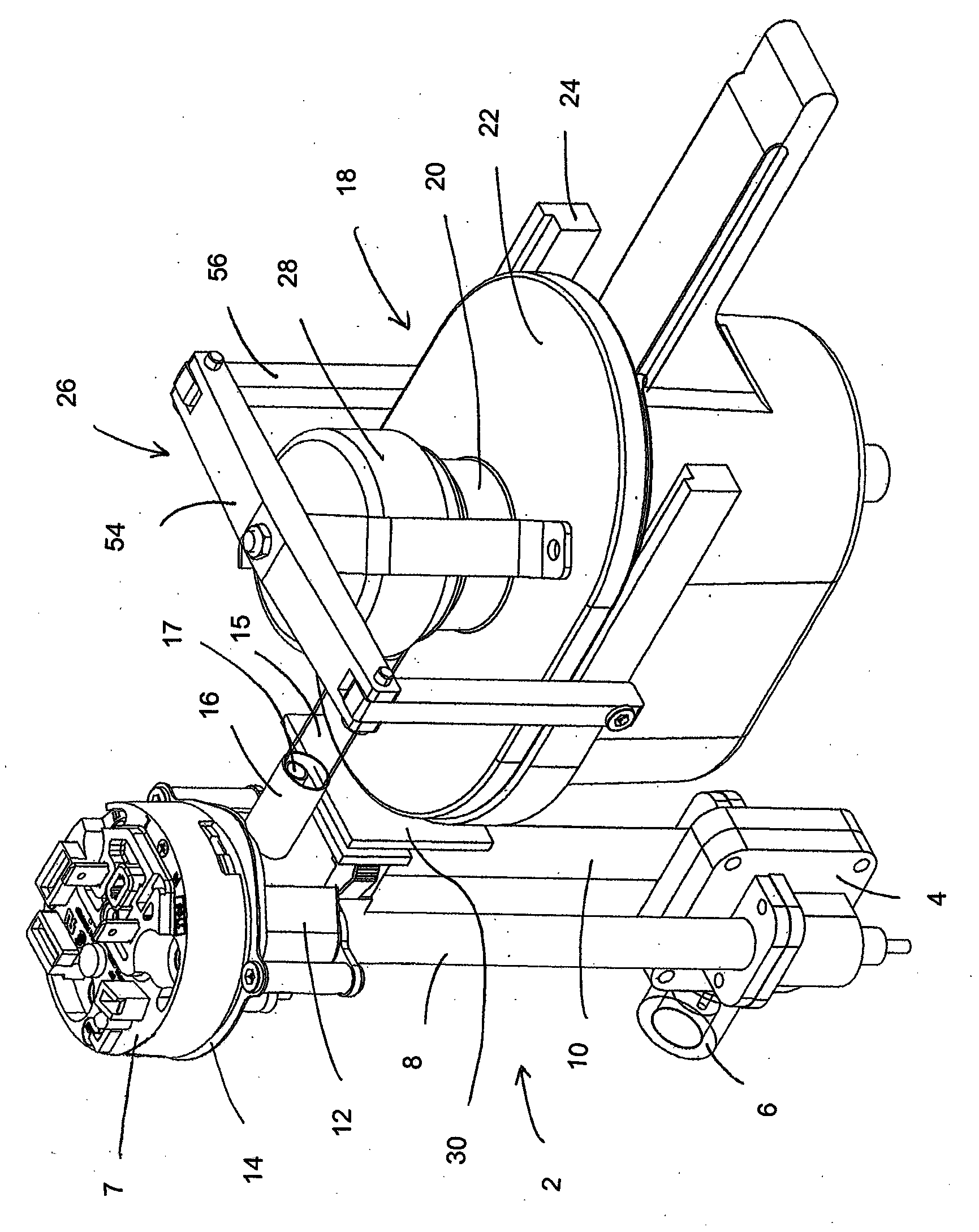
[0125] figure 1 Shown are some of the main internal components of an embodiment of the invention that may be used to make an infused beverage such as coffee. Some parts of the device, such as the housing and the water tank, have been omitted for clarity. From figure 1 In can be seen a vertical water heater 2 comprising a water distribution plenum block 4 at its lower end. Water enters the distribution booster block 4 from a side inlet 6 which is connected to a water tank and a centrifugal or reciprocating pump (not shown). The pressurization block 4 distributes water between two parallel flow heater sections 8 , 10 .

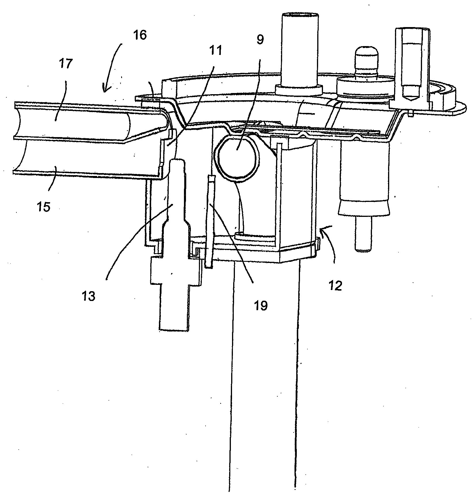
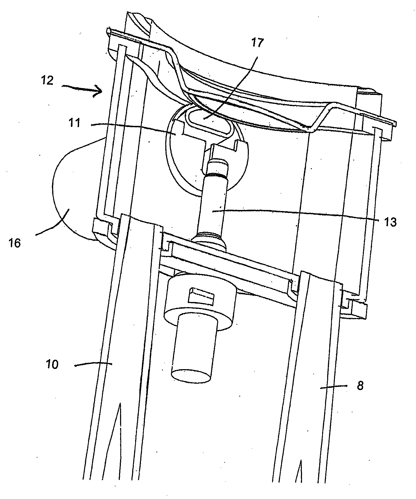
[0126] At the downstream (upper) end of the flow heater sections 8 , 10 is a boiling pool 12 . This is formed by a deep-drawn stainless steel cup fitted under the nearly circular stainless steel element head 14 . The boiling pool 12 has an outlet pipe 16 projecting laterally to supply heated water to a nose section 18 of the device.

[0127] In the arrange...


PUM


Abstract

An infusion beverage making apparatus (100) comprises a liquid heater, an infuser (140) for receiving beverage solid and conveying means for conveying heated liquid from the liquid heater onto the beverage solids. The apparatus (100) is configured to operate in at least one phase in which heated liquid is passed from the liquid heater through the beverage solids and in another phase in which steam is passed through at least a portion of the conveying means. A quantity of water is heated to boiling by the liquid heater and a steam pressure allowed to develop as a result which is sufficient to force steam through at least a portion of the conveying means.

Description

technical field [0001] The present invention relates to apparatus for heating a liquid to produce hot or boiling water, for example for an infusion beverage maker such as a coffee machine. Background technique [0002] Conventional coffee makers include a large thermal mass formed by a number of different components that all need to be hot before a hot cup of coffee can be prepared. These parts generally include the large thermoblock heater, the group head, the group holder (which holds the coffee grounds), the coffee bed itself, the cups, and anything from the heater to the outlet. Interconnecting lines, these parts may all be cold at startup. Therefore, if a volume of heated liquid (could be less than 50ml for espresso) is pumped through the machine right after start-up, much of this heat will be lost to the cold parts. Therefore, it can be understood that this will result in the water being cooled to a temperature well below the optimum temperature for brewing coffee (...

Claims


Application Information

Patent Timeline
Patent Type & Authority Applications(China)
IPC IPC(8): A47J31/60A47J31/56
CPCA47J31/002A47J31/56A47J31/60
Inventor 伊恩·费纳文森特·约瑟夫·加维詹姆斯·豪伊特乔纳森·迈克尔·怀特
Owner STRIX LTD
Learn More