a hair puller

A hair pulling device and hair clamping technology, which is applied in clothing, hairdressing equipment, scorched hair roots, etc., can solve the problems of affecting the pulling force, low work efficiency, and hair pulling device failure

Active Publication Date: 2016-11-16
中山市雷泰电器制造有限公司
View PDF8 Cites 0 Cited by
  • Summary
  • Abstract
  • Description
  • Claims
  • Application Information

AI Technical Summary

Problems solved by technology

But its working efficiency is low, no group of clip components can only clamp the hair once in one revolution, and its structure determines that more groups of depilation components cannot be added in the circumferential direction of the depilation device components, because this will affect its depilation strength, and greatly increase its production cost
On the other hand, the clamping and opening of the clip assembly needs to be realized by a spring, and the spring is prone to failure after a long time of use, which will inevitably lead to the failure of the hair puller

Method used


Image

  • a hair puller
  • a hair puller
  • a hair puller

Examples


Embodiment Construction

[0023] Below in conjunction with accompanying drawing and specific embodiment the present invention is described in further detail:

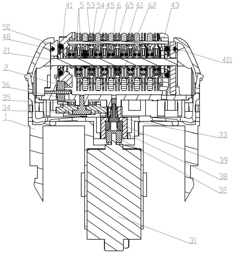
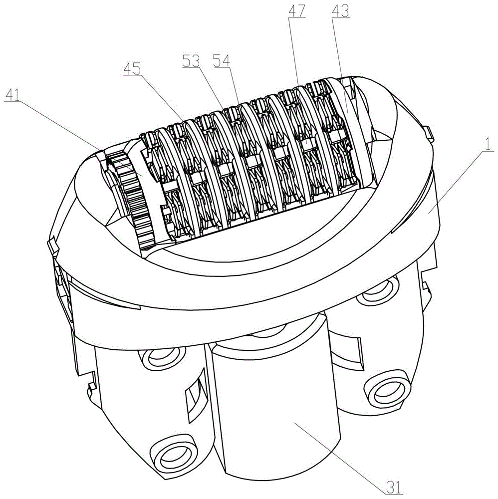
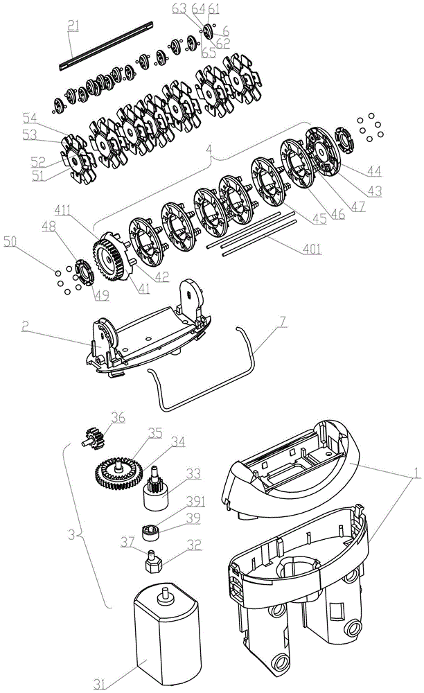
[0024] Such as Figure 1 to Figure 8 As shown, a hair puller includes a body 1, the body 1 is provided with a hair clip support 2 and a driving device 3, the clip hair support 2 is provided with a winding shaft 21 and is driven by the driving device 3 to rotate around the winding shaft 21 The turret4. Around the shaft 21 is a cross-shaped rod. Turntable 4 comprises the tail end block 43 that is located on the clip hair support 2 and the transmission block 41 that can be driven to rotate by driving device 3, is provided with a plurality of linking between the tail end block 43 and the transmission block 41 and will be adjacent to each other. The connecting block 45 separated by the clip assembly 5 also includes a plurality of serial connection columns 401 that connect the transmission block 41, the connection block 45, and the tail end block 43...


PUM


Abstract

The invention relates to a hair puller, which comprises a fuselage, on which a hair clamping bracket and a driving device are arranged, on the hair clamping bracket there is a rotating frame driven by the driving device to rotate around a shaft, and the upper edge of the rotating frame is There are multiple sets of clamping components that rotate with the turret in the axial direction around the shaft. The technical points are that the clamping components include a left clip and a right clip. The left clip is provided with a plurality of left branch leaves. The right The clip is provided with a right branch leaf that cooperates with the left branch leaf to grip the hair, and there are a plurality of gripping power blocks that can squeeze the gripping assembly to clamp and open when the turret rotates around the axis, and the gripping The bracket is provided with an elastic clamping piece axially clamping the rotating frame, the clamping assembly and the clamping power block. The invention has the advantages of simple structure, high hair-plucking efficiency and convenient assembly and disassembly.

Description

【Technical field】 [0001] The invention relates to a hair puller. 【Background technique】 [0002] The epilator is generally used for plucking body hair, and the existing epilator mainly has low working efficiency. Chinese patent CN201120445351.5 discloses an electric hair-plucking device, which mainly includes a hair-pulling device assembly and a motor drive device. Sheet assembly and return spring, its clip assembly includes stationary clip and movable clip. The clip hair is realized by the cylindrical cam and the spring when the clip assembly is rotated to realize the clamping and opening of the movable clip relative to the stationary clip. It has compact structure and low noise. But its working efficiency is low, no group of clip components can only clamp the hair once in one revolution, and its structure determines that more groups of depilation components cannot be added in the circumferential direction of the depilation device component, because this will affect its ...

Claims


Application Information

Patent Timeline
Patent Type & Authority Patents(China)
IPC IPC(8): A45D26/00
Inventor 吴让攀
Owner 中山市雷泰电器制造有限公司
Why Eureka
Try Eureka