
Prediction system and prediction method for line cross moment in lane changing process of straight road

A forecasting system and forecasting method technology, which is applied to the input parameters of external conditions, control devices, transportation and packaging, etc., can solve the problems of complicated parameter acquisition, and the forecasting method cannot be well applied, and achieves the effect of improving the forecasting level.

Active Publication Date: 2014-02-19
CHANGAN UNIV
View PDF7 Cites 7 Cited by
  • Summary
  • Abstract
  • Description
  • Claims
  • Application Information

AI Technical Summary

Problems solved by technology

However, the distribution of lateral acceleration collected during the actual lane change shows that the variation range of the lateral acceleration is small during the normal lane change process, and this range is usually related to drift, so the lateral acceleration caused by the lane change behavior is separated from the acceleration signal. Acceleration is a more complex problem
[0004] Generally speaking, there are not many prediction methods related to TLC at present. Although some prediction methods proposed by researchers have good theoretical depth, these prediction methods involve many parameters, and the vehicles in the actual road driving process The acquisition of these parameters is inherently complicated, which makes these prediction methods unable to be better applied.

Method used


Image

  • Prediction system and prediction method for line cross moment in lane changing process of straight road
  • Prediction system and prediction method for line cross moment in lane changing process of straight road
  • Prediction system and prediction method for line cross moment in lane changing process of straight road

Examples


Embodiment Construction

[0031] The present invention will be further described below in conjunction with the accompanying drawings:

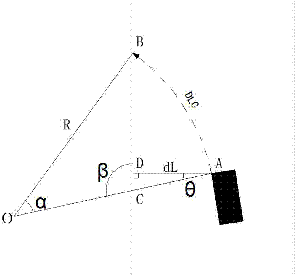
[0032] The purpose of the present invention is to propose a method for predicting the time of crossing the line in the lane changing process of the straight road section based on the geometric parameter analysis based on the distance data between the vehicle and the lane line measured by the visual sensor, so as to realize the prediction of the time of crossing the line in the lane changing process of the straight road section.

[0033] In order to achieve the above purpose, it is necessary to install the device first. The installation process is as follows: install the vision sensor on the outer front end of the vehicle. is ±635cm, and the output frequency is 10Hz. The vision sensor measures the distance between the vehicle and the lane line in real time based on the principle of machine vision. The output parameters include the distance between the vehicle and the le...


PUM


Abstract

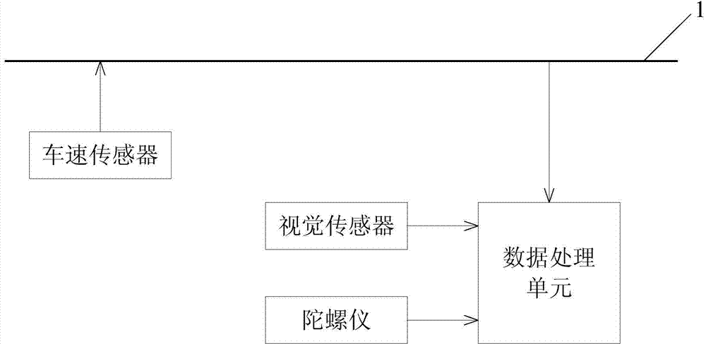
The invention belongs to the technical field of early warning of lane changing of straight roads, and discloses a prediction system and a prediction method for line cross moment in a lane changing process of a straight road. The prediction system for the line cross moment in the lane changing process of the straight road comprises a vehicle-mounted CAN (controller area network) bus, a data processing unit, a vehicle speed sensor, a visual sensor and a gyroscope, wherein the vehicle speed sensor is arranged on a vehicle transmission; the visual sensor is used for measuring the distance between a vehicle and a lane line; the gyroscope is arranged in the center of a chassis of the vehicle; the visual sensor is arranged at the front end of the outside of the vehicle; the output end of the vehicle speed sensor is electrically connected with the vehicle-mounted CAN bus; and a signal input end of the data processing unit is respectively electrically connected with a signal output end of the gyroscope, a signal output end of the visual sensor and the vehicle-mounted CAN bus.

Description

technical field [0001] The invention belongs to the technical field of lane change warning in straight road sections, and particularly relates to a line crossing time prediction system and prediction method in a lane change process of straight road sections. Background technique [0002] The lane change warning system can automatically analyze the possibility of collision with other vehicles behind during the lane change process, and prompt the driver according to the severity of the conflict. Essentially, a traffic conflict between vehicles occurs because different vehicles arrive at the same location at the same time. By analyzing the motion state of the vehicle during the lane changing process, it can be seen from the time series that the starting point of the traffic conflict is that the self-vehicle crosses the lane line and enters the target lane during the lane changing process. Therefore, if the TLC (Time to Line Crossing) can be accurately predicted, the risk of th...

Claims


Application Information

Patent Timeline
Patent Type & Authority Applications(China)
IPC IPC(8): B60W40/10
CPCB60W40/10B60W2520/00B60W2555/00
Inventor 王畅徐远新石涌泉鲁玉萍
Owner CHANGAN UNIV
Learn More