Deepwater mining annular pipeline lifting and conveying device

A ring-shaped pipeline and conveying device technology, which is applied in the direction of conveying bulk materials, conveyors, transportation and packaging, etc., can solve the problems of sinking to the bottom in the rigid lifting pipe, the proportion of minerals is large, and the conveying efficiency is low. Weight, improve conveying efficiency, and solve the effect of international technical problems

Inactive Publication Date: 2014-02-19
裘尧云
View PDF8 Cites 8 Cited by
  • Summary
  • Abstract
  • Description
  • Claims
  • Application Information

AI Technical Summary

Problems solved by technology

[0003] Patent No. 01136098.4 "Hydraulic Lifting Seabed Mineral Method and Device" provides a pipeline transportation method, which transports the minerals collected by the deep-water ore collection device to the For surface mining ships, the rigid lifting pipe is transported vertically upwards, so it cannot be transported vertically for a long distance upwards, and the specific gravity of minerals is larger than that of water. The minerals can no longer be transported upwards, causing the minerals to sink to the bottom in the rigid lifting pipe, so the transport efficiency is extremely low and the practicability is poor

Method used


Image

  • Deepwater mining annular pipeline lifting and conveying device
  • Deepwater mining annular pipeline lifting and conveying device
  • Deepwater mining annular pipeline lifting and conveying device

Examples


Embodiment Construction

[0013] Embodiments of the present invention will be further described below in conjunction with the accompanying drawings.

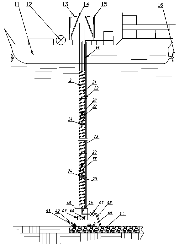
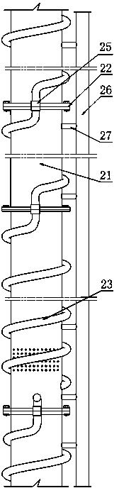
[0014] The length of the total support pipe 2 is according to the design requirements, and is formed by fixing more than one section of support pipe 21 through the connector support pipe flange 22, such as figure 1 shown.

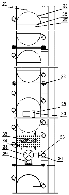
[0015] In the inner cavity of every section support tube 21, there are buoyancy air chambers 20, 20' formed by upper and lower semicircular cover plates 31 and baffle plates 32 and the inner walls of part support tube 21. Only the length is different, and the buoyancy air The cabin 20' length is greater than the buoyancy air cabin 20, can reduce the weight of the whole device, as image 3 shown.

[0016] According to the needs of the site situation, more than two buoyancy air chambers 20' are installed in a section of support pipe every 100-1000 meters, and the first electric hydraulic pump is installed in the buoyancy air chamber 2...


PUM


Abstract

The invention discloses a deepwater mining annular pipeline lifting and conveying device. A main supporting pipe is integrally formed by fixing at least two segments of supporting pipes through connecting pieces. A buoyancy air cabin with an electric hydraulic pump station, a buoyancy air cabin and a middle boost pump are arranged in the supporting pipes and an electric power control cable is arranged in a cable groove in the outer sides of the supporting pipes. The upper end and the lower end of the main supporting pipe are connected with a mining vessel lifting device and a traction steel wire rope respectively. A lifting and conveying pipe is an annular spiral pipeline which is fixed on the supporting pipes in a surrounding mode. The upper end and the lower end of the lifting and conveying pipe are connected with an ore sand output pump and a flexible conveying pipe respectively. The lifting and conveying pipe performs lifting and conveying in a spiral mode, the gravitational effect due to mineral substance free fall in the pipeline is avoided, and therefore the lifting and conveying distance is longer. Due to the fact that the electric hydraulic pump station is arranged in the buoyancy air cabin in the supporting pipes, the underwater weight of the whole device is reduced, in addition, working power is provided for the middle boost pump and an all-direction propeller, and the deepwater mining annular pipeline lifting and conveying device is safer and more reliable in use. Deepwater is led in through the all-direction propeller and a diversion hole to generate reacting force to prevent the supporting pipes from being twisted and deformed.

Description

technical field [0001] The invention relates to a lifting conveying device for deep-water mining, in particular to a deep-water mining annular pipeline lifting and conveying device for conveying deep-water minerals to surface mining ships, which can be widely used in deep-water manganese nodules, mud ore, polymetallic ore and Mining and transportation of underwater combustible ice. Background technique [0002] At present, the lifting and conveying technology of deep-water mining is still an international technical problem and has become the technical bottleneck of deep-water mining. [0003] Patent No. 01136098.4 "Hydraulic Lifting Seabed Mineral Method and Device" provides a pipeline transportation method, which transports the minerals collected by the deep-water ore collection device to the For surface mining ships, the rigid lifting pipe is transported vertically upwards, so it cannot be transported vertically for a long distance upwards, and the specific gravity of min...

Claims


Application Information

Patent Timeline
Patent Type & Authority Applications(China)
IPC IPC(8): B65G53/04B65G67/60
Inventor 裘尧云曹健舞裘磊博
Owner 裘尧云
Why Eureka
Try Eureka