
Hydraulic drive oil tube elevator

A technology of elevators and oil pipes, which is applied in the direction of drilling pipes, casings, drilling equipment, etc., can solve the problems of not being able to meet the needs of intelligent control in oilfields, poor locking effects, and potential safety hazards, and achieve convenient operation, reduce operators, Safe and reliable locking effect

Inactive Publication Date: 2014-02-19
TONGHUA CITY FORWARD GASOLINEEUM MACHINERY
View PDF0 Cites 5 Cited by
  • Summary
  • Abstract
  • Description
  • Claims
  • Application Information

AI Technical Summary

Problems solved by technology

In specific use, the oil pipe is inserted into the elevator body through the opening on the elevator body, and the locking ring is rotated by the rotation of the manual handle to block the opening and prevent the oil pipe from falling off. The need for personalized control, the locking effect is poor, and there are potential safety hazards

Method used


Image

  • Hydraulic drive oil tube elevator

Examples


Embodiment Construction

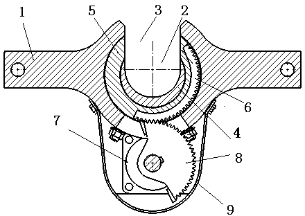
[0010] see figure 1 , The names of the parts are as follows: Elevator body 1, central hole 2, gap 3, open tooth ring 4, locking ring 5, arc-shaped rack 6, hydraulic motor 7, sector gear 8, shield 9.

[0011] see figure 1 , a hydraulically driven oil pipe elevator includes an elevator body 1, a center hole 2 for holding the oil pipe in the middle of the elevator body 1, a gap 3 for the oil supply pipe to enter and exit on one side of the center hole 2, and a crescent in the center hole 2 Shaped open tooth ring 4 and coaxial rotatable locking ring 5. One side of the outer surface of the locking ring 5 is inlaid with an arc-shaped rack 6, and there is a sector gear 8 driven by a hydraulic motor 7 outside the elevator body 1, which passes through the elevator body and meshes with the arc-shaped rack 6 of the locking ring to drive the arc-shaped rack 6 Rotate to seal the gap 3. The hydraulic motor 7 is fixed on the outer surface of the elevator body 1 by bolts and has a shield...


PUM


Abstract

The invention relates to ascending or descending oil tube tools in oil field petroleum drilling and production operations, in particular to a hydraulic drive oil tube elevator. The hydraulic drive oil tube elevator is suitable for the lifting operation of suspending an oil tube with a tube diameter of 1.9''-41 / 2'' and an external upset oil tube. The hydraulic drive oil tube elevator comprises an elevator body and a central hole which is formed in the middle of the elevator body and used for clamping the oil tube, an opening allowing the oil tube to pass through is formed in one side of the central hole, and an open thread ring and a locking ring capable of rotating and moving are arranged in the central hole in a lining mode. An arc-shaped gear rack is embedded in the outer surface of the locking ring, and a sector gear driven by a hydraulic motor is arranged outside the elevator body and penetrates through the elevator body to be meshed and connected with the arc-shaped gear rack of the locking ring. A protection cover is arranged outside the hydraulic motor. Hydraulic driving is adopted, operating personnel can be reduced, and the hydraulic drive oil tube elevator is a key component for achieving well repair automation. The hydraulic control locking structure is adopted, the hydraulic drive oil tube elevator is suitable for oil field intelligent control, remote control is achieved, the operation is convenient, and locking is safe and reliable.

Description

[0001] technical field [0002] The invention relates to a tool for lifting or lowering oil pipes in oil drilling operations in oil fields, that is, hydraulically driven oil pipe elevators. It is suitable for lifting oil pipes with pipe diameters of 1.9''~4 1 / 2'' (diameter φ48.3~φ114.3mm) and externally thickened oil pipes. Background technique [0003] In the prior art, the BD series tubing elevators are locking ring elevators, which are divided into two types: single-head or double-head. The upper aperture of the single head has a set of locking ring devices; the upper and lower apertures of the double heads each have a set of locking ring devices. Elevator body and locking ring are the main parts of hanging oil holding pipe. The locking ring is placed in the eccentric groove of the elevator body, with the help of the handle and the handle shaft, it can be adjusted at 115 0 Change the opening and locking position of the locking ring within a certain range. The handle is...

Claims


Application Information

Patent Timeline
IPC IPC(8): E21B19/06
Inventor 李勇徐科邢励君徐延凯苏强
Owner TONGHUA CITY FORWARD GASOLINEEUM MACHINERY
Learn More