Spiral direct-drive electric-hydraulic proportional flow valve with hollow permanent-magnet alternating-current servo motor

An AC servo, electro-hydraulic proportional technology, used in engine components, servo motor components, fluid pressure actuation devices, etc., can solve problems such as increasing equipment costs, immature multi-stage cartridge valve technology, and high prices.

Inactive Publication Date: 2014-02-19
XI AN JIAOTONG UNIV
View PDF9 Cites 3 Cited by
  • Summary
  • Abstract
  • Description
  • Claims
  • Application Information

AI Technical Summary

Problems solved by technology

However, additional hydraulic circuits are required and the maintenance cost is high, and the technology of multi-stage cartridge valves in the domestic market is not yet mature
Especially at present, cartridge valves are used in many large-scale forging equipment in China to realize functions such as flow control and unloading. The working conditions of these forging equipment make the requirements for corresponding cartridge valves continue to increase, and it is usually because The failure of auxiliary components to meet the requirements limits the development of domestic forging equipment in terms of tonnage and control accuracy
Although many domestic hydraulic valve manufacturers continue to carry out independent research and development, foreign imported cartridge valves still account for the vast majority in the field of forging equipment, and the price is high, which in disguise increases the cost of equipment

Method used


Image

  • Spiral direct-drive electric-hydraulic proportional flow valve with hollow permanent-magnet alternating-current servo motor

Examples


Embodiment Construction

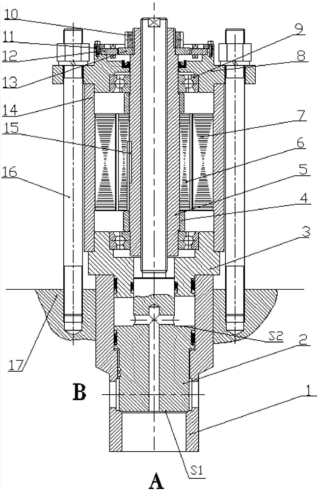
[0016] The present invention will be described in detail below in conjunction with the accompanying drawings.

[0017] As shown in the figure, the hollow permanent magnet AC servo motor helical direct drive electro-hydraulic proportional flow valve includes a valve core 2, which is placed in the valve sleeve 1, and the top of the valve sleeve 1 is connected with a lower cover plate 3, The lower end surface of the lower cover plate 3 forms a cavity with the end surface of the valve core 2, and a central hole is opened in the valve core 2 to communicate with the cavity, so that the inlet high-pressure oil enters the cavity to balance the pressure of the valve port, and the upper part of the valve core 2 passes through the lower cover The valve stem in the center hole of the plate 3 is processed with external thread, which plays the role of a screw, and is connected with the long nut 5. The long nut 5 is connected with the servo motor rotor 6 through the flat key 15, and the outer...


PUM


Abstract

A spiral direct-drive electric-hydraulic proportional flow valve with a hollow permanent-magnet alternating-current servo motor comprises a valve element. The valve element is disposed in a valve sleeve, a lower cover plate is connected with the top of the valve sleeve, a cavity is formed by the lower end face of the lower cover plate and the end face of the valve element, and a central hole communicated with the cavity is formed in the valve element. An outer thread is processed on a valve rod, penetrating a central hole of the lower cover plate, on the upper portion of the valve element. The valve rod is in matched connection with a long nut. The long nut is connected with a rotor of the servo motor, the lower end face of a shell of the servo motor is connected with the lower cover plate, and the lower end of an upper press plate is pressed on the upper end face of the shell of the servo motor. Threads are arranged at two ends, positioned on the upper press plate and the lower cover plate, of the long nut. Angular contact ball bearings are mounted face to face. The long nut extends out of the outer end of the upper press plate to mount a rotary transformer rotor. A rotary transformer stator is fixed with the upper press plate through a cover plate. Rotary movement of the rotor of the servo motor is transformed into linear motion of the valve element through a sliding screw mechanism formed by the long nut and the upper portion of the valve element. Opening and closing of the valve is realized through control on rotation of the motor. By the spiral direct-drive electric-hydraulic proportional flow valve, accuracy is improved and cost is reduced.

Description

technical field [0001] The invention relates to the technical field of electro-hydraulic servo valves, in particular to a hollow permanent-magnet AC servo motor helical direct-drive electro-hydraulic proportional flow valve. Background technique [0002] The traditional electro-hydraulic servo valve consists of an electro-mechanical converter, a hydraulic amplifier and a feedback detection device. In the case of large flow, multi-stage valves are widely used. It contains a pilot stage valve as the control stage. The pilot valve often uses a nozzle stopper. Plate type, jet tube type and slide valve type and other structures. The service life and reliability of traditional servo valves are closely related to the degree of pollution of hydraulic oil. The hydraulic system where the servo valve is installed must be thoroughly cleaned. The nozzle baffle type and jet tube type have high requirements on the oil, and the cleanliness needs to be within 5μ In the following, the contam...

Claims


Application Information

Patent Timeline
Patent Type & Authority Applications(China)
IPC IPC(8): F15B13/02F16K31/04F16K31/06
Inventor 赵升吨朱牧之
Owner XI AN JIAOTONG UNIV
Why Eureka
Try Eureka