Biomass combustion furnace

A biomass combustion furnace and combustion tank technology, which is applied in combustion methods, control combustion, combustion equipment, etc., can solve the problems of low work efficiency, insufficient fuel combustion, low utilization rate, etc., and achieve smooth and fast ignition process. The effect of utilization

Active Publication Date: 2014-02-19
泉州恒灼热力机械科技有限公司
View PDF12 Cites 7 Cited by
  • Summary
  • Abstract
  • Description
  • Claims
  • Application Information

AI Technical Summary

Problems solved by technology

As the combustion progresses, the ashes and unburned materials produced by the fuel combustion will block the air intake holes on the grate to a certain extent and affect the air supply combustion, so the ashes produced by the material combustion need to be used during the combustion process. It is discharged in time, but the cleaning must be carried out after the fuel is burned, so once the air intake hole is blocked, the furnace will stop working and clean up to delay time; The holes are only distributed at the bottom of the combustion chamber, and there is a certa

Method used


Image

  • Biomass combustion furnace
  • Biomass combustion furnace
  • Biomass combustion furnace

Examples


Embodiment 1

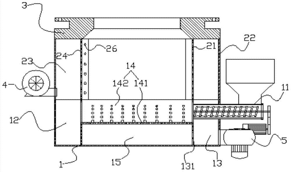
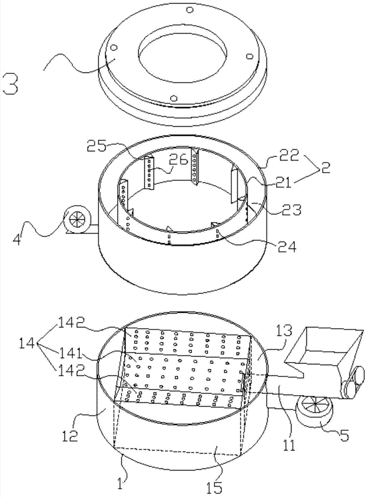
[0025] refer to figure 1 , figure 2 , image 3 , a biomass combustion furnace, comprising a combustion base (1), a combustion chamber (2) disposed on the combustion base (1), a flange (3) disposed on the combustion chamber (2), and a The first blower (4) outside the combustion chamber (2), the combustion chamber (2) consists of a cylindrical wall (21), is located outside the cylindrical wall (21) and is connected to the cylindrical wall (21) The concentric shell (22) is composed of a cylindrical wall (21) and the shell (22) to form an air inlet chamber (23). The air inlet chamber (23) communicates with the first blower (4), and the cylindrical wall On the body (21), 8 rows of air inlets (24) connected with the air inlet chamber (23) are distributed in 8 rows and each row is arranged vertically around the axis; the air inlet holes (24) are straight holes, and the air inlet holes ( 24) The side of the hole on the inner wall of the cylindrical wall (21) is provided with a win...

Embodiment 2

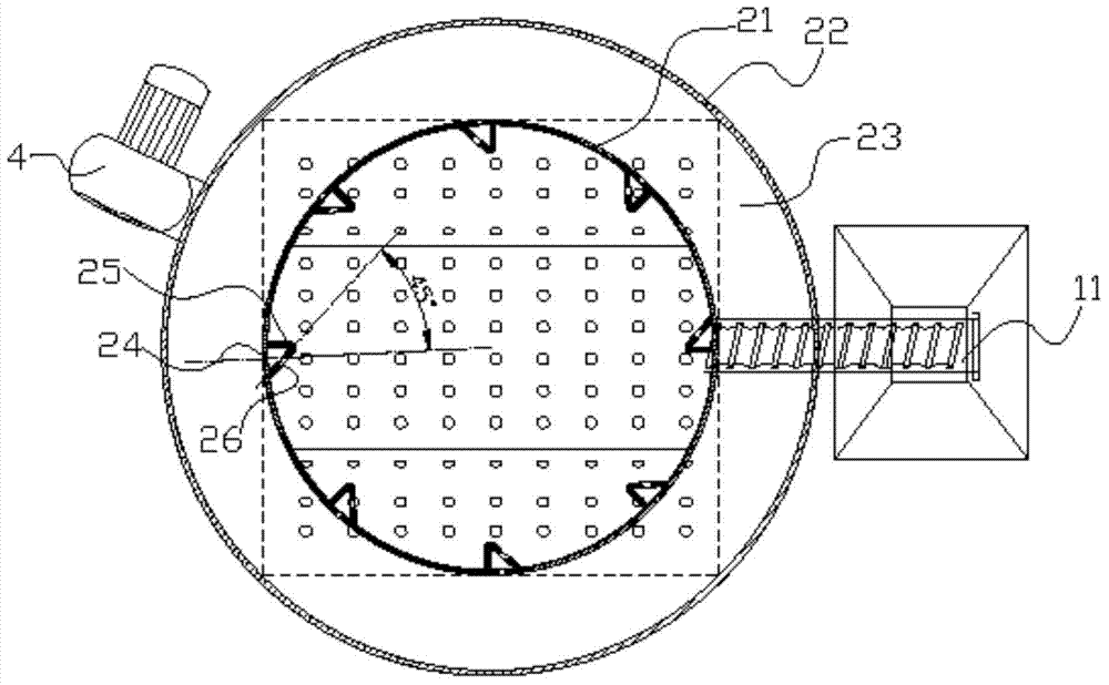
[0027] refer to Figure 4 , Figure 5, a biomass combustion furnace, including a combustion base (1), a combustion chamber (2) disposed on the combustion base (1), a flange disposed on the combustion chamber (2), and a combustion chamber ( 2) The outer first air blower, the combustion chamber (2) consists of a cylindrical wall (21), a shell (22) that is located outside the cylindrical wall (21) and concentric with the cylindrical wall (21) The air inlet chamber (23) is formed between the cylindrical wall (21) and the casing (21), the air inlet chamber (23) communicates with the first blower (4), and the cylindrical wall (21) is surrounded by 12 rows of 10 longitudinally arranged air inlet holes (24) communicated with the air inlet chamber (23) are evenly distributed on the axis, and the air inlet holes (24) are located on the inner wall of the cylindrical wall (21). A windshield (27) is provided on the side to deflect the wind entering from the air inlet (24), and the includ...


PUM

PropertyMeasurementUnit
Angleaaaaaaaaaa

Abstract

The invention relates to combustion furnaces and provides a biomass combustion furnace which is suitable for heating heat transfer oil furnaces, superheated steam furnaces, air heating furnaces, water heaters and the like. Through the biomass combustion furnace, biomass can be enabled to be combusted sufficiently, utilization rate of biomass combustion is increased, combustion ash can be removed timely during combustion, and pollution due to the fact that air flow is discharged into air is avoided. The biomass combustion furnace comprises a combustion base, a combustion chamber arranged on the combustion base and a flange arranged on the combustion chamber, the combustion base comprises a combustion base body, a feed device and a second air blower, an ash storage box is arranged at one end of the combustion base body, an air inlet box is arranged at the other end of the combustion base body, a combustion tank which is communicated with the ash storage box and the air inlet box is arranged on the upper portion of the combustion base body, air vents are formed in the combustion tank, the combustion tank, the bottom surface and the lateral surface of the combustion base body, the ash storage box and the air inlet box form a cavity jointly, an air inlet communicated with the air inlet box is formed in the lateral surface, connected with the air inlet box, of the cavity, the feed device is arranged outside the combustion base body and passes through the air inlet box to be led to the combustion groove, and the second air blower is communicated with the air inlet box.

Description

technical field [0001] The invention relates to a combustion stove, in particular to a biomass combustion stove. Background technique [0002] In recent years, the development, recycling and production of biomass fuels have received unprecedented attention. The raw material of biomass fuel is mainly obtained from agricultural and forestry waste, which is inexhaustible. Through a series of deep processing, biomass particles or powder are usually produced, and the two are burned separately and converted into biomass energy to provide alternative energy for industry. , not only solves the problem of agricultural and forestry waste disposal, but also reduces the emission of CO2 and harmful gases to the atmosphere. [0003] In the existing biomass combustion equipment, biomass is usually burned in a combustion chamber first, and the heat energy generated by it enters the second chamber to heat the furnace body. Since the flue gas generated after biomass combustion can be further...

Claims


Application Information

Patent Timeline
IPC IPC(8): F23B40/06F23J1/00F23L9/02F23N3/00
Inventor 杨恒灼
Owner 泉州恒灼热力机械科技有限公司
Why Eureka
Try Eureka