
Touch panel and method for forming touch panel

A touch panel and one-sided technology, applied in the input/output process of data processing, instruments, electrical digital data processing, etc., can solve the problems of manpower consumption, cost, complicated process steps, and difficult alignment of wires 106 and 110 , to achieve the effect of fast and convenient manufacturing process and simple manufacturing process

Inactive Publication Date: 2014-02-19
YOMORE TECH
View PDF3 Cites 0 Cited by
  • Summary
  • Abstract
  • Description
  • Claims
  • Application Information

AI Technical Summary

Problems solved by technology

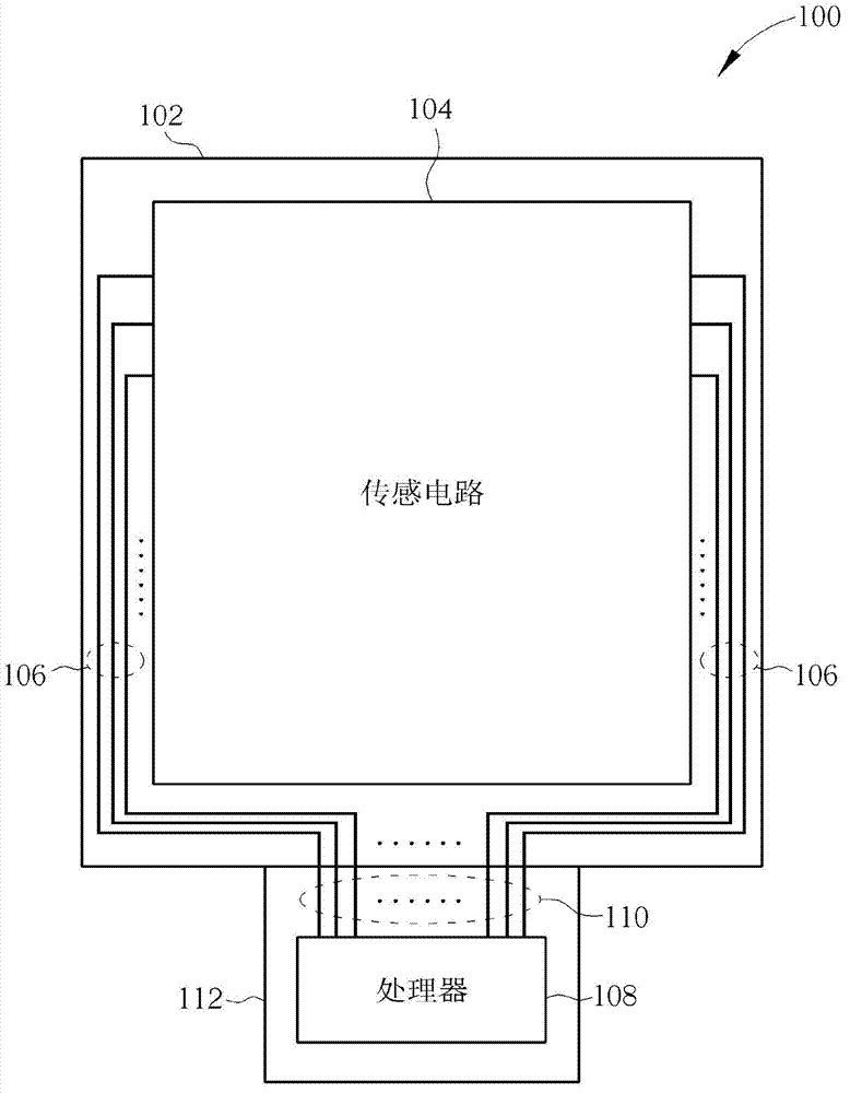
[0003] However, the prior art has the following disadvantages: first, the protective glass 102 and the flexible circuit board 112 need to be processed separately, and the pressing between the protective glass 102 and the flexible circuit board 112 consumes manpower and cost; During the pressing process of the glass 102 and the flexible circuit board 112, very precise alignment is required to ensure the bonding of the wire 106 and the wire 110
However, since the line width of the wire 106 and the wire 110 is very narrow, it is difficult for the wire 106 and the wire 110 to align; thirdly, during the pressing process of the protective glass 102 and the flexible circuit board 112, the pressure during the pressing process It may cause the wire 106 and the wire 110 to break; fourth, in order to join the conductive glass on the protective glass 102, the silver paste and the copper on the flexible circuit board 112, the process steps become more complicated; When the wire 106 is made by sputtering, etc., if there is ink on the surface of the protective glass 102, the protective glass 102 will not be easily sputtered.
[0004] Therefore, for manufacturing the touch panel 100, the prior art is not a good manufacturing method

Method used


Image

  • Touch panel and method for forming touch panel
  • Touch panel and method for forming touch panel
  • Touch panel and method for forming touch panel

Examples


Embodiment Construction

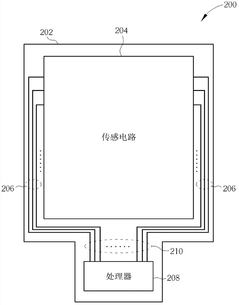
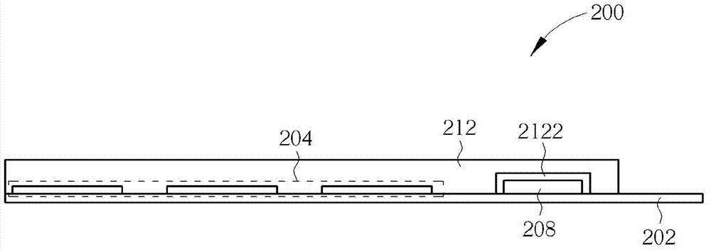
[0027] An embodiment of the present invention provides a touch panel 200, wherein the touch panel 200 includes an adhesive film 202 and a protective glass 212, and the adhesive film 202 can be polyethylene terephthalate (PET) Film or polyethylene naphthalate (polyethylene naphthalate, PEN) film. But the present invention is not limited to the film 202 being a polyethylene terephthalate film or a polyethylene naphthalate film. That is, the adhesive film 202 can be other optically transparent adhesive molds. Please refer to figure 2 , figure 2 is a schematic diagram for explaining the adhesive film 202 . Such as figure 2 As shown, the sensing unit of the sensing circuit 204 , the first wire 206 coupled to the sensing circuit 204 , and the second wire 210 coupled between the first wire 206 and the processor 208 are formed on the adhesive film 202 . The sensing unit of the sensing circuit 204 , the first wire 206 and the second wire 210 can be formed on the adhesive film 2...


PUM


Abstract

The invention discloses a touch panel and a method for forming the touch panel. The touch panel comprises an adhesive film and a protection glass. A sensing unit of a sensing circuit, a first guide line coupled with the sensing circuit and a second guide line coupled between the first guide line and a processor are formed on the adhesive film. The adhesive film is attached below the protection glass in an attaching manner. Therefore, by the aid of the touch panel and the method, the touch panel can be quick and convenient in processing, poor connection of the first guide line and the second guide line can be avoided, precise positioning is not required, disconnection of the first guide line and the second guide line is not caused, and the touch panel is easier in processing.

Description

technical field [0001] The present invention relates to a touch panel and a method for forming a touch panel, in particular to a touch panel in which a sensing circuit of the touch panel and wires coupled to the sensing circuit and a processor are formed on an adhesive film. Panel and method of forming a touch panel. Background technique [0002] Please refer to figure 1 , figure 1 It is a schematic diagram illustrating the touch panel 100 in the prior art. Such as figure 1 As shown, the silver paste is generally laid on the protective glass (such as a transparent cover plate such as glass) 102 by sputtering or printing to form a sensing circuit (including a plurality of sensing units) 104 or to couple sensing circuits. Area wire 106. Then, the flexible printed circuit board (Flexible Printed Circuit, FPC) 112 provided with the processor 108 and the wire 110 coupled to the processor 108 is arranged by pressing, so that the wire 110 coupled to the processor 108 and the w...

Claims


Application Information

Patent Timeline
Patent Type & Authority Applications(China)
IPC IPC(8): G06F3/041
Inventor 林招庆李文定倪君凯
Owner YOMORE TECH
Learn More