Systems and methods for detecting changes in the presence of objects in a magnetic field

A technology of magnetic fields and objects, applied in the size/direction of magnetic fields, electromagnetic wave systems, measuring magnetic variables, etc., which can solve the problems of waste of transmission energy and inefficiency

Active Publication Date: 2016-01-13
TEXAS INSTR INC
View PDF8 Cites 0 Cited by
  • Summary
  • Abstract
  • Description
  • Claims
  • Application Information

AI Technical Summary

Problems solved by technology

Inductive methods are quite inefficient even over relatively short ranges, wasting a lot of transmitted energy

Method used


Image

  • Systems and methods for detecting changes in the presence of objects in a magnetic field
  • Systems and methods for detecting changes in the presence of objects in a magnetic field
  • Systems and methods for detecting changes in the presence of objects in a magnetic field

Examples


Embodiment Construction

[0016] The systems and methods disclosed herein for detecting changes in the presence of objects in a magnetic field may be used in wireless transmitter applications, for example. However, the disclosed systems and methods may be applied to other systems where detection of the presence or changes in the presence of objects in a magnetic field is advantageous. Example embodiments may be included in wireless charging applications where the presence of an object may be determined before charging begins.

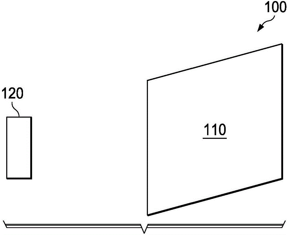
[0017] figure 1 A system block diagram of a system 100 for detecting changes in the presence of objects in a magnetic field is provided. System 100 includes object 120 and charger device 110 in an example wireless power system. In an example embodiment, the charger device 110 determines the presence of the object 120 . After determining the presence of the object, the charger device 110 may be tasked with charging the object 120 after generating the magnetic field and determi...


PUM


Abstract

The system detects changes in the presence of objects in the magnetic field generated from the coil (205). A low amplitude signal close to the resonance frequency is injected into the coil (205) until the system reaches equilibrium. Feedback is measured at this point. The feedback signal may be measured as at least one of several signals such as, but not limited to, the voltage across the resonant capacitor (203), the current in the coil (205) or between the resonant capacitor (203) and the coil (205) voltage between. A change in the steady state response represents a change in the presence of the device.

Description

technical field [0001] The present disclosure relates generally to magnetic fields, and more specifically, to wireless power transfer. Background technique [0002] Wireless energy transfer or wireless power is the transfer of electrical energy from a source to an electrical load without interconnecting wires. Wireless transmission is useful in situations where interconnecting wires are inconvenient, dangerous, or impossible. For wireless power transfer, efficiency is an important parameter. [0003] A common form of coupling in wireless power transmission is inductive coupling. Wireless power transfer systems typically consist of electromagnetically coupled transmit and receive coils. Coil coupling can be used to transfer energy originating from the primary side over a distance to the secondary side. Electromagnetic induction wireless transmission technology is near-field over a distance equal to several times the diameter of the device and close to a quarter of the wav...

Claims


Application Information

Patent Timeline
Patent Type & Authority Patents(China)
IPC IPC(8): G01R33/02H02J17/00
CPCG01R33/0041G01R33/028H01F38/14H04B5/0037H04B5/0081H02J50/12H02J50/90H02J7/0049H02J50/10
Inventor E·G·澳汀格
Owner TEXAS INSTR INC
Why Eureka
Try Eureka