
Liquid quenching holding furnace

A holding furnace and liquid quenching technology, applied in safety devices, metal processing equipment, casting equipment, etc., can solve the problems of difficult research work, impossible to observe the evolution of the internal structure of metals, and the inability to continuously explore the role of metal solidification process, etc. To achieve the effect of controllable and solidification speed

Inactive Publication Date: 2014-02-26
SHENYANG POLYTECHNIC UNIV
View PDF3 Cites 2 Cited by
  • Summary
  • Abstract
  • Description
  • Claims
  • Application Information

AI Technical Summary

Problems solved by technology

[0002] Because the solidification process of metals is carried out in an opaque state, usually when studying the metal structure, we can only study the structure of the final state of the metal after solidification. It is impossible to observe the evolution of the internal structure of the metal before solidification, and thus cannot be continuously explored. The effect of various influencing factors on the metal solidification process has brought great difficulties to the research work.

Method used


Image

  • Liquid quenching holding furnace
  • Liquid quenching holding furnace
  • Liquid quenching holding furnace

Examples


Embodiment 1

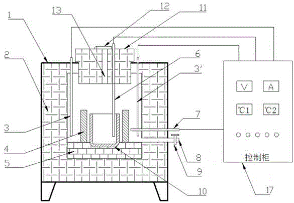
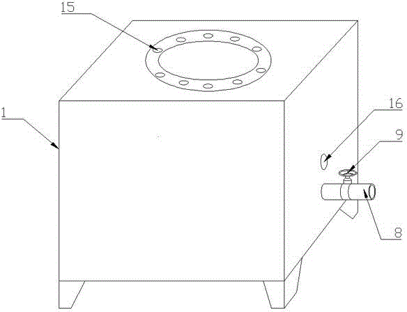
[0021] Example 1: The smelted liquid quenching sample of ductile iron can choose a silicon molybdenum rod as the heating rod (3), and assemble it through the 10 heating rod insertion holes (15) above the furnace body (1) after selection.

[0022] Select argon as the inert gas, and connect it through the inert gas inlet tube (8).

[0023] The minimum temperature of the control cabinet (17) is set to 1150°C, the inert gas is introduced to discharge the air, the electricity is heated to the set temperature, and the crucible (10) can be put into it for preheating.

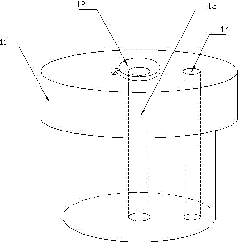
[0024] The spheroidized molten iron is poured into the preheated crucible (10) at 1350°C, and then quickly transferred to the furnace, and the pre-designed annular cold iron (4) is selectively added according to the cooling rate requirements , cover the furnace cover (11), stop the delivery of inert gas, and close the air flow control valve (9).

[0025] Extract the liquid quenched sample according to the temperature ...

Embodiment 2

[0027] Example 2: A liquid quenching sample for Al-Si alloy smelting A silicon carbide rod can be selected as the heating rod (3), and assembled through the 10 heating rod insertion holes (15) above the furnace body (1) after selection.

[0028] Select argon as the inert gas, and connect it through the inert gas inlet tube (8).

[0029] The minimum temperature of the control cabinet (17) is set to 585°C, the inert gas is introduced to discharge the air, the electricity is heated to the set temperature, and the crucible (10) can be put into it for preheating.

[0030] Inject the molten aluminum into the preheated crucible (10) at 720°C and quickly transfer it to the furnace, and selectively add the pre-designed annular chiller (4) according to the cooling rate requirements, cover Put on the furnace cover (11), stop the delivery of inert gas, and close the air flow control valve (9).

[0031] Extract the liquid quenched sample according to the temperature displayed on the cont...


PUM


Abstract

The invention provides a liquid quenching holding furnace. The solidification process of metal is conducted under the opaque state so that the microstructure evolution situation inside the metal before solidification can not be observed, and therefore great difficult is brought to research work. According to the liquid quenching holding furnace, the crystal precipitation behavior inside the metal before solidification can be researched under the situation of a laboratory, the solidification process of the metal can be simulated inside the furnace, the temperature can be rapidly lowered in a forced mode with the combination of an annular chilling block, so that the solidification speed is controllable, and finally the microstructure forms in molten metal at different moments and high temperature can be kept outside the furnace through the liquid quenching method. Multiple liquid quenching samples with the same chemical components and the same treatment conditions can be obtained from the molten metal of the same furnace so that the growth situation of crystals in the solidification process can be observed conveniently and the crystal precipitation behavior of the crystals at each temperature and each moment before solidification can be continuously and effectively researched.

Description

technical field [0001] The invention relates to an experimental method for observing the microstructure in the process of metal solidification, and belongs to the field of material preparation and processing. Background technique [0002] Because the solidification process of metals is carried out in an opaque state, usually when studying the metal structure, only the structure of the final state of the metal after solidification can be studied. It is impossible to observe the evolution of the internal structure of the metal before solidification, and thus cannot be continuously explored. The effects of various influencing factors on the metal solidification process have brought great difficulties to the research work. Contents of the invention [0003] In order to overcome the shortcomings of the above-mentioned prior art, the liquid quenching and holding furnace of the present invention realizes the simulation of the metal solidification process in the furnace through th...

Claims


Application Information

Patent Timeline
IPC IPC(8): B22D46/00
Inventor 尤俊华蒋立鹏姜珂张新宁高民强朱绍晨
Owner SHENYANG POLYTECHNIC UNIV
Learn More