Rolling ball type washing machine
A washing machine, rolling ball technology, applied to other washing machines, washing machines with containers, washing devices, etc., can solve the problems of increased cleaning capacity, secondary pollution, dirt storage, etc., and achieve simplified internal structure and easy cleaning , high cleanliness effect
- Summary
- Abstract
- Description
- Claims
- Application Information
AI Technical Summary
Problems solved by technology
Method used
Image
Examples
Embodiment 1
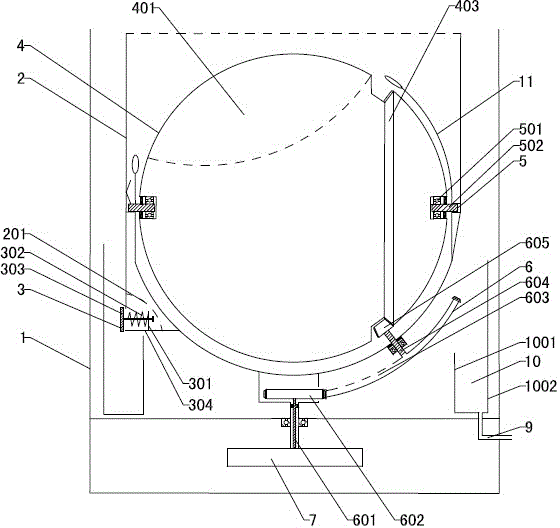
[0034] Refer to attached figure 1 with 6: A kind of rolling ball washing machine, comprises the rolling ball 4 that suits from the inside to the outside successively, dries the inner tube 2 and the outer cylinder body 1, and the rolling ball 4 is used as the washing drum, and the clothes that need to be cleaned are placed inside, and the power of one side is used to The device 7 drives the spin-drying inner cylinder 2 to rotate. The rolling ball 4 is a spherical shell with a pick-and-place opening 401 on the top. The two ends of the central axis of the roller ball 4 are connected to both sides of the inner wall of the drying inner tube 2 through the rotating connection device 5, and the rolling ball 4 can rotate with the horizontal central axis in the drying inner tube 2, and the rolling ball 4 and the drying inner tube 2 can be rotated synchronously with the central axis in the vertical direction by the power device 7; the side of the lower part of the drying inner cylinder ...
Embodiment 2
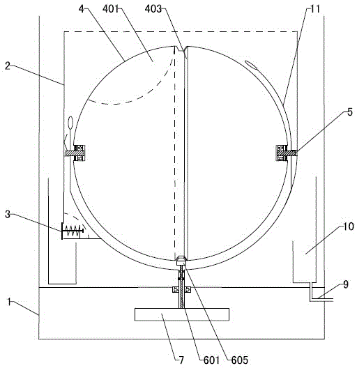
[0044] Refer to attached figure 2 : the rotation guide groove 403 is arranged on the longitudinal centerline of the rolling ball 4, the transmission mechanism 6 is a gear transmission mechanism, and is correspondingly installed directly below the bottom of the drying inner cylinder 2, the transmission mechanism 6 includes a meshing gear 605 and a transmission shaft 601, the transmission shaft Engagement gear 605 is installed on the top of 601, and the bottom is connected to the output end of power unit 7; the top of engagement gear 605 is engaged with the bottom of rotation guide groove 403.
[0045] When working, the power unit 7 transmits power to the meshing gear 605 through the transmission shaft 601, and the meshing gear 605 drives the rolling ball 4 to rotate. Other settings and working principles are the same as those in Embodiment 1.
Embodiment 3
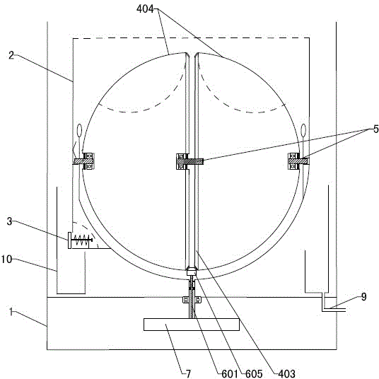
[0047] Refer to attached image 3 with 7 The rolling ball 4 is divided into two hemispherical shells 404 that are arranged symmetrically, and the tops of the two hemispherical shells 404 are respectively provided with pick-and-place openings 401, and the middle parts of the two hemispherical shells 404 are connected by a group of rotating connecting devices 5. In one body, two hemispherical shells 404 are symmetrically provided with meshing teeth around the edges of the connecting plane. There is a gap between the two hemispherical shells 404. The two meshing teeth are spliced to form a rotation guide groove 403. The rotation guide groove The bottom of 403 is meshed with the meshing gear 605 of the transmission mechanism 6 through meshing teeth. The spherical sides of the two hemispherical shells 404 are respectively connected to the inner wall of the drying inner cylinder 2 through a set of rotating connecting devices 5 .
[0048] The rotating connection device 5 connecte...
PUM
 Abstract
Description
Claims
Application Information
 - R&D
- Intellectual Property
- Life Sciences
- Materials
- Tech Scout
- Unparalleled Data Quality
- Higher Quality Content
- 60% Fewer Hallucinations
Browse by: Latest US Patents, China's latest patents, Technical Efficacy Thesaurus, Application Domain, Technology Topic, Popular Technical Reports.
© 2025 PatSnap. All rights reserved.Legal|Privacy policy|Modern Slavery Act Transparency Statement|Sitemap|About US| Contact US: help@patsnap.com


